Diagram #5, Diagram #6, Diagram #7 – Derale Performance Direct Fit Jeep Wrangler Performance Electric Fan Kit User Manual
Page 3: Relay, Thermostat probe installation, Relay harness mouting, Wiring
Derale Performance, Los Angeles, CA
800.421.6288 www.derale.com
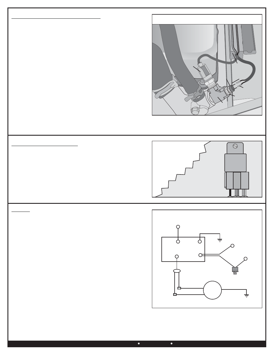
THERMOSTAT PROBE INSTALLATION
1.
Locate the factory engine temperature sensor right next to the
upper radiator hose on the front of the engine. (See Diagram #5)
2.
Carefully disconnect the factory temperature sensor wire plug.
3.
Temporarily remove the factory temperature sensor turning it
counter clockwise.
4.
Clean old thread sealant on factory temperature sensor.
5.
Locate the supplied 3/8” NPT Brass Tee. Using Teflon Tape or
suitable sealant, install the MALE end of the 3/8” NPT Brass Tee
into the vehicles 3/8” port. (See Diagram # 5)
6.
Rotate the 3/8” NPT Brass Tee until both female ports are facing
upward.
7.
Take the factory temperature sensor. Using Teflon Tape or
suitable sealant, install the factory temperature sensor into the
side port on the 3/8” NPT Brass Tee.
8.
Locate the supplied 3/8” x 1/8” Reducer Bushing. Using Teflon
Tape or suitable sealant, install the 3/8” x 1/8” Reducer Bushing
into the top port on the 3/8” NPT Brass Tee.
9.
Locate the supplied Thermostat Switch. Using Teflon Tape or
suitable sealant, install the Thermostat Switch into the 3/8” NPT
Reducer Bushing.
RELAY
RELAY
Mounting
Surface
Fan Belt
Fan Belt
Valve Cover
Valve Cover
Wire
Runner
Wire
Runner
Thermostat
Housing
Thermostat
Housing
Blue Female
Connectors
Blue Female
Connectors
3/8” NPT
Brass Tee
3/8” NPT
Brass Tee
3/8” x 1/8”
Reducer Bushing
3/8” x 1/8”
Reducer Bushing
Factory
Temp
Sensor
Factory
Temp
Sensor
Thermostat
Switch
Thermostat
Switch
Diagram #5
(Page 3)
Diagram #6
RELAY HARNESS MOUTING
1.
Taking into consideration wire routing preference, choose a
location near the vehicles Battery or under hood fuse panel.
Avoid mounting near HOT engine components.
2.
Using the Relay as a template, mark and drill a 5/32” hole in the
desired location.
3.
Using the #10 Sheet Metal Screw provided, install the Relay/Wire
Harness. (See Diagram #6)
WIRING
Using the Convoluted Tubing, 4” Zip Ties, extra Wire and Electrical
Connectors supplied, follow the instructions below. (See Diagram #7)
Warning: When extending wires, always use the identical gauge wire as
provided.
ELECTRIC FAN
BLACK Wire: Using a Blue #10 Ring Terminal and #10 Sheet Metal
Screw supplied, attach the Black wire to a good Chassis Ground (-).
GREY & Brown Wire: Using a Yellow Butt Connector supplied, attach
the Grey & Brown wires to the Orange wire on the Relay Wire
Harness.
THERMOSTAT SWITCH
Note: Wires running to the Thermostat Switch can be routed through the
plastic factory wire runner on the top of the engine. (See Diagram #5)
Diagram #7
To open: There are several plastic clips on each side of
the wire runner. Using a small screw driver, carefully release each clip.
Be careful not to break clips!
1.
Using a Blue Female Connector supplied, attach EITHER
terminal on the Thermostat Switch to the Yellow wire coming
from the Relay Wire Harness.
2.
Using a Blue Female Connector and Blue Wire Tap Connector supplied, attach the remaining terminal on the Thermostat
Switch to a Positive (+) switched ignition source.
Warning: If this wire is connected to a constant power source (battery) the electric fan will run after the vehicle has been shut
off and could ultimately affect battery performance.
Chassis
Ground (-)
Orange Fan
Positive (+)
Orange Fan
Positive (+)
30Amp Fuse
Ignition
Switch
Red
30
86
85
87
Green
Orange
Yellow
Black
Chassis
Ground (-)
12 Volt Positive (+)
Battery
Thermostat
Switch
RELAY
Override Circuit
(Optional)
FAN
MOTOR
Black
Grey
Brown
For illustrative purposes only.
Actual engine may vary!