Fault codes and troubleshooting – tmu vfd, 3 fault codes and troubleshooting – tmu vfd – R&M Materials Handling ELECTRIC CHAIN HOISTS LoadMate Chain Hoist TMU Motorized Trolley User Manual
Page 28
LM
TMU I&M MANUAL/EN/06.15.2009
28/38
This document and the information contained herein, is the exclusive property of R&M Materials Handling, Inc., and represents a non-public, confidential and proprietary trade secret
that may not be reproduced, disclosed to third parties, altered or otherwise employed in any manner whatsoever without the express written consent of R&M Materials Handling, Inc.
Copyright © (2009) R&M Materials Handling, Inc. All rights reserved.
4.3 Fault Codes and Troubleshooting – TMU VFD
m
WARNING: Do not touch any circuit components while the main AC power is on. High voltages
are supplied to the inverter (including the programming switches). Wait for at least three
minutes after the supply voltage has been switched off before performing any service on the
unit. Failure to adhere to this warning can result in injury.
If the TMU VFD malfunctions, a fault lamp blinks on and off. The blinking pattern continues until a new fault
occurs or until power is switched off. The fault codes are explained in the table below.
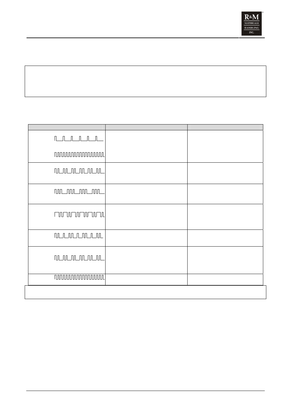
Table 12. TMU VFD Fault Code Troubleshooting Guide
LED Color, Blinking Pattern
Possible cause.
What to do.
GREEN
Lower input voltage.
GREEN
Over voltage.
Supply voltage exceeds the specification
allows.
Deceleration ramp time is too short.
Extend Deceleration time.
GREEN
Stall supervision / over current.
Brake does not open properly or an
obstacle is on the track.
Incorrect motor dependent parameter setup.
Adjust air gap. Repair/replace brake.
Check that the motor parameter settings
(switch S4) match the motor(s) supplied.
GREEN
Deceleration ramp supervision.
Deceleration ramp has not been followed.
Supply voltage greater than specification
allows.
Reset to longer Deceleration ramp time.
Check voltage of all supply phases at
terminal X1.
GREEN
Inverter over temperature.
Motor current is too high (bearing problem,
obstacle on the track, brake does not open
properly).
Ambient temperature is too high.
Repair bearing problem. Remove
obstacle. Adjust air gap or repair or
replace brake.
Use a larger rated inverter.
GREEN
Under voltage.
Supply voltage < specification allows
Correct the input power supply problem.
Check for single-phase problem.
RED
Short circuit.
Break down in motor cable insulation.
Break down in motor winding insulation.
Inverter transistor failure.
Switch main power off.
Replace the motor cables.
Check motor resistance. Replace the
motor.
Replace inverter.
RED
Microprocessor fault.
Due to high electrical noise environment.
Switch power off for 10 seconds, then
back on.
)
Note: The latest active fault is always removed from the memory when power is switched off.
Drive will not run even though inverter is not in a fault condition:
y
Motor will not start if DC-bus voltage too high (above 745V), this occurs if any line-to-line voltage
exceeds 480V+5% = 504V. If line voltage cannot be reduced, install step-down transformer in inverter
branch circuit.
y
Check the supply voltage phases at terminal X1.
y
Check the control signals at terminal X1.
y
Check that the control voltage is correct. Rating plate is located on the left side of the inverter.
y
Check all parameter selections, especially the motor parameters (switch S4).
y
Check that the selected motor parameters (switch S4) correspond to the appropriate motor type.
y
Check that the microprocessor starts running. Both the green and red indicator LEDs blink once as the
inverter is powered up. After the one second initializing time, only the green LED should be lit.
y
Check that the brake opens and closes properly. Check the brake air gap.
y
Check plug connection for intermittent operations.