Mounting position of drive unit, Mounting the drive unit, Removing the drive unit – R&M Materials Handling ELECTRIC CHAIN HOISTS LoadMate Chain Hoist TMU Motorized Trolley User Manual
Page 18: Inspection and service of the drive unit, 4 mounting position of drive unit, 5 mounting the drive unit, 6 removing the drive unit, 7 inspection and service of the drive unit
LM
TMU I&M MANUAL/EN/06.15.2009
18/38
This document and the information contained herein, is the exclusive property of R&M Materials Handling, Inc., and represents a non-public, confidential and proprietary trade secret
that may not be reproduced, disclosed to third parties, altered or otherwise employed in any manner whatsoever without the express written consent of R&M Materials Handling, Inc.
Copyright © (2009) R&M Materials Handling, Inc. All rights reserved.
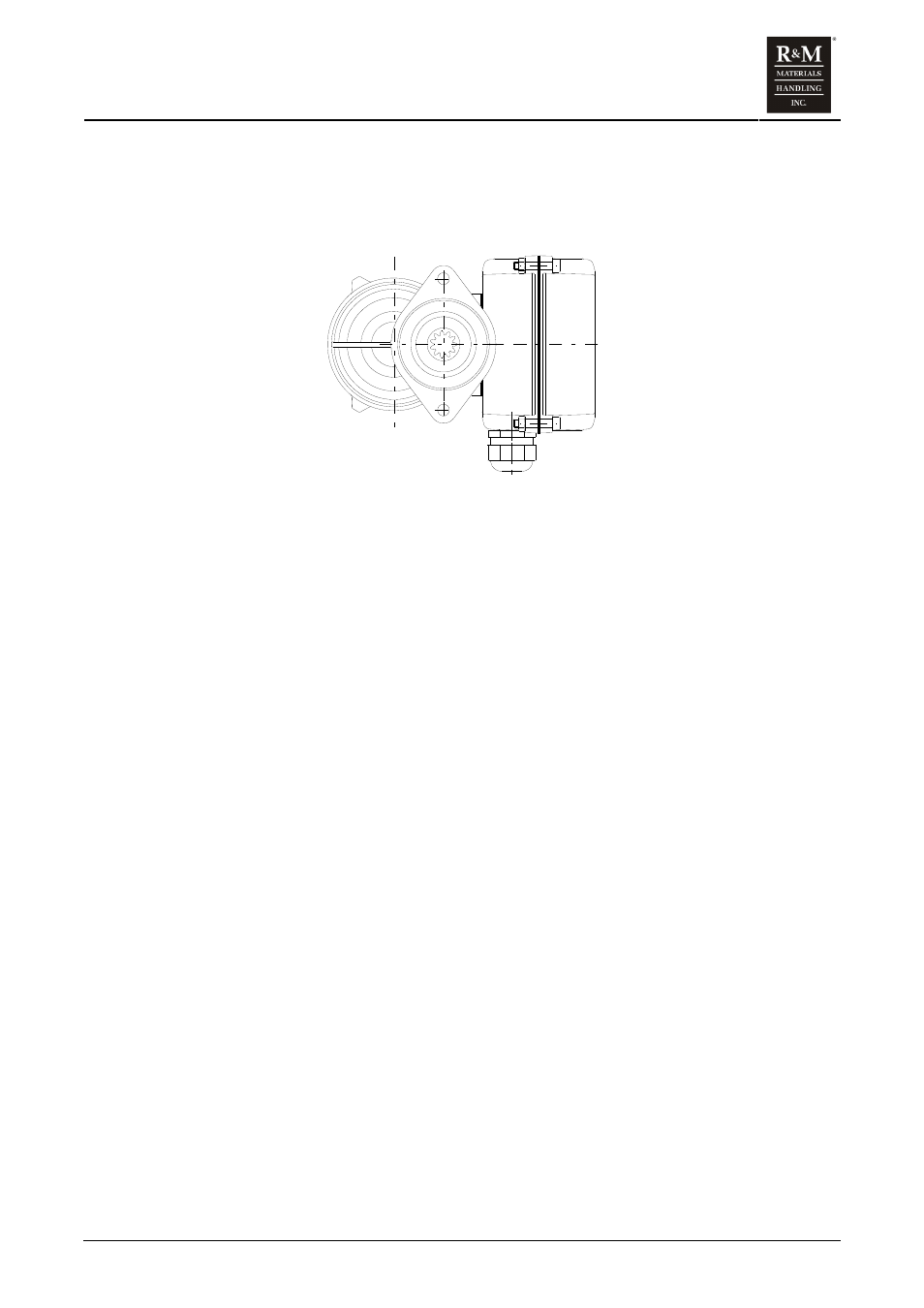
3.4 Mounting Position of Drive Unit
Figure 7. Positioning of the TMU Drive Unit
The TMU drive unit is to be positioned so that the control enclosure is located to the side of the motor, with
the power cable outlet pointing down as shown above.
Other mounting positions of the drive are not recommended because they reduce the cooling effectiveness
and may cause overheating of the controls.
3.5 Mounting the Drive Unit
y
Be sure the main power supply is switched off - to avoid electrical hazard.
y
Align the pinion teeth with the wheel gear teeth. Push the drive unit against the trolley side plate.
y
Rotate the machinery to the proper mounting position. Note: the motor brake prevents the free rotation of
the motor. So either release the brake or raise the drive wheels off the rail.
y
Insert the mounting bolts. Use lock washers
y
Tighten the mounting bolts by hand until snug.
y
If the drive wheels are raised up, lower the wheels down before beginning the final tightening of the
mounting bolts. Note: Wheels must lie on the track when tightening the mounting bolts to ensure that no
excessive loads are directed toward the secondary shaft. Recommended tightening torque for M8 bolt is
18 ft-lbs [24 Nm].
y
Connect the power cable plug to the hoist.
3.6 Removing the Drive Unit
y
Disconnect power and lockout disconnecting means on the crane/hoist.
y
Disconnect the power cable plug from the hoist.
y
Loosen and remove the mounting bolts.
y
Remove the drive unit from the trolley side plate.
3.7 Inspection and Service of the Drive Unit
y
Check the tightness of the mounting bolts.
y
Check the traveling motion: acceleration and deceleration.
y
Check the brake for wear of the friction linings. If necessary, clean the brake and replace the friction
linings.
y
Check the air gap of the brake.
y
Check that the inverter or contactors operate correctly.
y
Gears are lubricated with semi-fluid grease. See Preventative Maintenance section for grease type.