Connecting the unit – B&B Electronics 7506GX2-SX - Manual User Manual
Page 14
(Revised 2010-7-30)
Page 14 of 158
Connecting the Unit
For 10/100/1000 Base-T ports, plug a Category 5E twisted pair cable into the RJ45 connector. Connect the
other end to the far end station. Verify that the LNK/ACT LEDs are ON once the connection has been
completed. To connect any port to another device (end node, Switch or Repeater), use a standard Category
5E straight through or crossover cable
with a minimum length of one meter and a
maximum length of 100 meters.
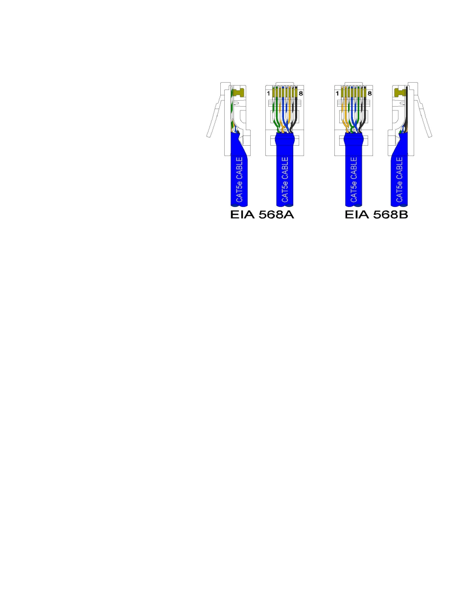
N-Tron recommends the use of pre-
manufactured Cat5E cables to ensure the
best performance. If this is not an option
and users must terminate their own ends
on the Cat5E cables; one of the two color
coded standards shown to the right should
be utilized. If a user does not follow one
of these two color code standards then the
performance and maximum cable distance
will be reduced significantly, and may
prevent the switch from establishing a
link.
For LC style fiber optic connections, remove the dust cap from the SFP modules and connect the fiber optic
cables. The TX port should be connected to the RX port of the far end station. The RX port should be
connected to the TX port of the far end station.
Warning: Creating a port to port connection on the same switch (i.e. loop) is an illegal operation and
will create a broadcast storm which will crash the network!