B&B Electronics DSC-200_300 - Manual User Manual
Page 18
4.5 Options Register
The Options Register allows software to identify the DSC-200/300 as a Quatech
Enhanced Serial Adapter. It also allows software to set the UART clock rate multiplier.
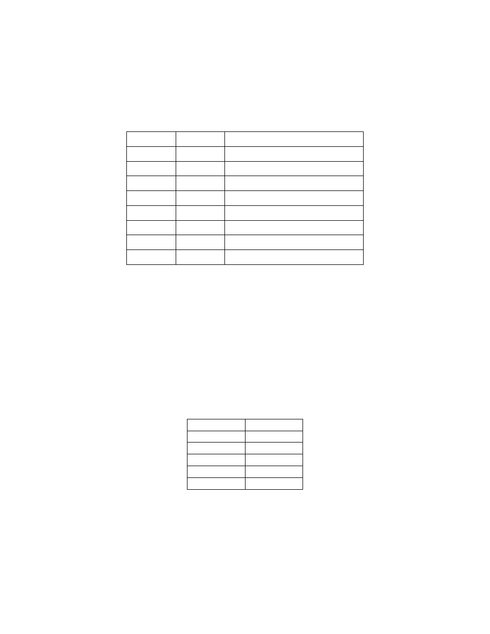
Figure 10 shows the structure of the Options Register.
The powerup default of the Options Register is all bits zero.
Clock rate multiplier bit 0
RR0
0
Clock rate multiplier bit 1
RR1
1
(reserved, 0)
-
2
(reserved, 0)
-
3
(reserved, 0)
-
4
(reserved, 0)
-
5
ID bit 0
ID0
6
ID bit 1
ID1
7 (MSB)
Description
Name
Bit
Figure 10--- Options Register bit definitions
4.5.1 Enhanced Serial Adapter Identification
The ID bits are used to identify the DSC-200/300 is a Quatech Enhanced Serial Adapter.
Logic operations are performed such that the values read back from these bits will not necessarily
be the values that were written to them. Bit ID1 will return the logical-AND of the values written
to ID[1:0], while bit ID0 will return their exclusive-OR.
Software can thus identify a Quatech Enhanced Serial Adapter by writing the ID bits with
the patterns shown in the "write" column of Figure 11, then reading the bits and comparing the
result with the patterns in the "read" column. Matching read patterns verify the presence of the
Options Register.
0
1
1
1
1
0
0
1
1
0
1
0
0
0
0
0
ID0
ID1
ID0
ID1
Read
Write
Figure 11 --- ID bit write/read table
Quatech DSC-200/300 User's Manual
16