B&B Electronics 855-12840--49 - Manual User Manual
Page 17
13
Power Supply Installation
When installing a redundant power supply module into a powered-on 12-Slot
chassis, B&B Electronics recommends setting the ON/OFF switch on the module
(if present) to OFF. After installing the power supply, turn its switch ON.
If the redundant power supply module does NOT have an ON/OFF switch, B&B
Electronics recommends powering-down the chassis before installing the power
supply. Turn the chassis back ON after installing the power supply.
LED Operation
Each media conversion module features diagnostic LEDs (see diagrams below)
that provide information on features and ports.
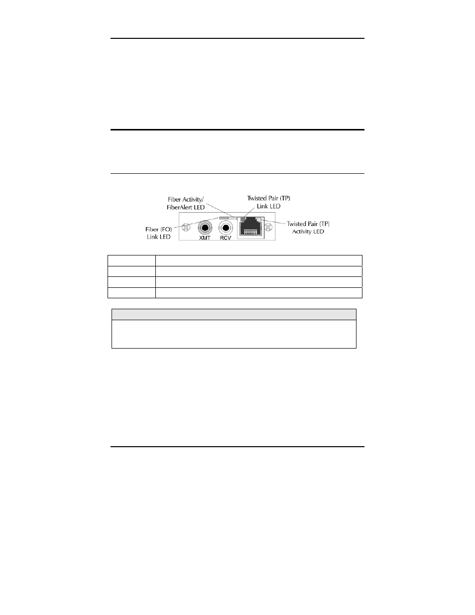
LEDs on on McPIM TP/FO
The LED functions for McPIM TP/FO with fiber ports are as follows:
FO LINK
Glows green when link is established on the fiber port.
FIBERALERT Glows amber when FiberAlert is enabled
TP LINK
Glows green when link is established on the TP port.
ACTIVITY
Blinks amber when data is being passed on either port.
NOTE
On a -40 McPIM TP/FO, the TP RCV, TP LNK and FO Link LEDs flicker at a rate
proportional to the rate that passes on the ports; when the rate is low, the LEDs
flicker visibly, while they appear to glow when the rate is high.