B&B Electronics ZXT9-IO-222R2 - Quick Start Guide User Manual
Page 5
pn 8590R1-ZXTx-IO-x-2011QSG –Peer-to-Peer Mode
Now the Zlinx Xtreme I/O modules are ready to
communicate Peer-to-Peer mode with default setup.
Detailed setup can be done using the Zlinx Manager
using the following steps.
S
S
t
t
a
a
r
r
t
t
Z
Z
l
l
i
i
n
n
x
x
I
I
/
/
O
O
M
M
a
a
n
n
a
a
g
g
e
e
r
r
Connect the USB port of your PC to the Zlinx Xtreme I/O
module using a USB cable.
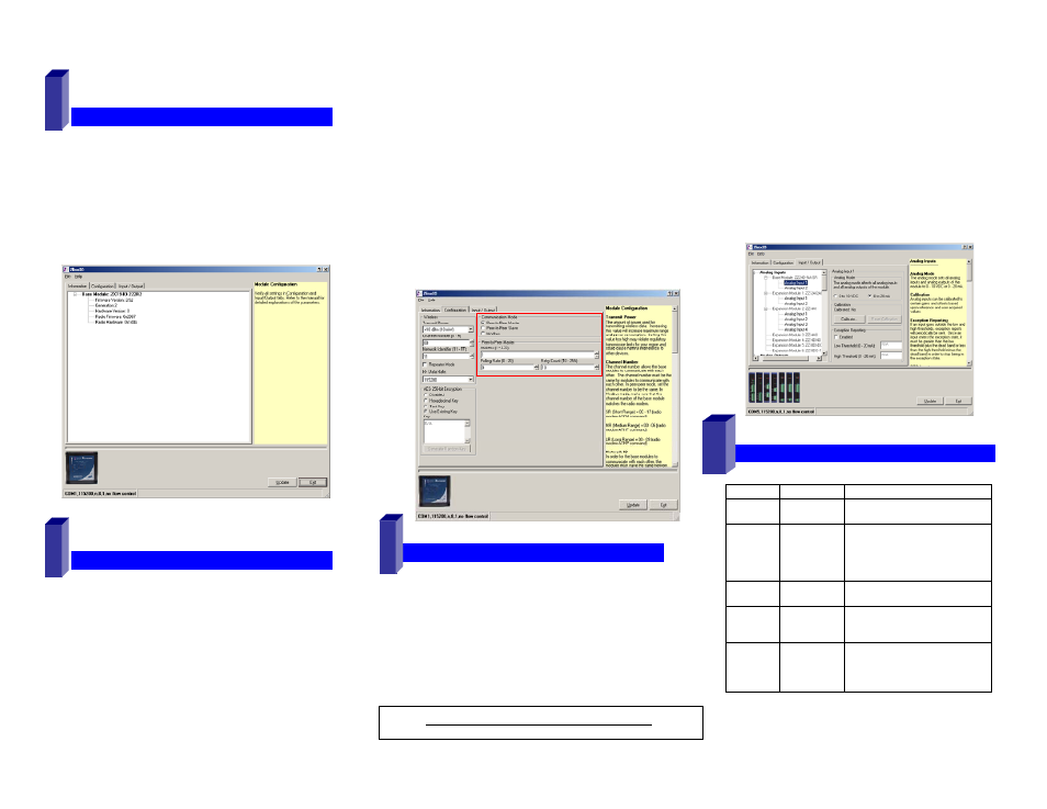
Click Start\Programs\B&B Electronics\Zlinx\Zlinx
Manager\Zlinx Manager, then click Zlinx I/O and then
Zlinx I/O Configuration. It will auto-search for attached
Zlinx Xtreme I/O Module on startup. Zlinx I/O will open
and display the Information tab showing the I/O model
number, version numbers and firmware rev levels.
C
C
o
o
n
n
f
f
i
i
g
g
u
u
r
r
e
e
C
C
o
o
m
m
m
m
u
u
n
n
i
i
c
c
a
a
t
t
i
i
o
o
n
n
M
M
o
o
d
d
e
e
s
s
P2P Master Configuration – From Configuration tab
Configure Wireless settings:
o
Select the desired RF Transmit Power
o
Set the Channel Number.
o
Set the Network Identifier.
o
Set Repeater checkbox if desired. Note that ONLY
the (ZXT9-IO- xx) modules supports this mode.
o
Set encryption key.
Select the communication mode to ‘P2P Master’ Mode.
Set the P2P Master address as desired.
Set Polling Rate and Retry Count.
Click Update to save configuration.
P2P Slave Configuration – From Configuration tab
Configure Wireless settings:
o
Select the desired RF Transmit Power
o
Set the Channel Number to match that of master.
o
Set the Network Identifier to match that of master.
o
Set encryption key the same as that of master.
Select the communication mode to ‘P2P Slave’ Mode.
Set the P2P Salve address to match that of Master.
Click Update to save configuration
C
C
o
o
n
n
f
f
i
i
g
g
u
u
r
r
e
e
I
I
n
n
p
p
u
u
t
t
/
/
O
O
u
u
t
t
p
p
u
u
t
t
Set Digital Inputs for Discrete. Counter configuration is
not applicable to Peer-to-Peer mode
o
Choose PNP or NPN selection as appropriate.
Each input is individually configurable.
Configure Digital Relay Outputs.
Enable the Fail Safe and Communications Fail Alarm if
necessary.
Configure each Analog Inputs and Outputs in one of the
following modes
7
o
0-5V, 0-10V, 0-20mA, 4-20mA
Set Exception Reporting for Analog Inputs and Fail Safe
settings for Analog Outputs if necessary.
Set Calibration option if you desire to better match a
sensor, or a portion of a signal, to the I/O.
Refer to appropriate sections in the Zlinx XtremeI/O
manual.
Click Update button to apply the settings.
O
O
p
p
e
e
r
r
a
a
t
t
i
i
o
o
n
n
10
LED
STATUS
FUNCTION
Power
Solid
Flash
Power applied
Communication Fail
RSSI
(8 LED
bar
graph)
0
1-3
4-6
7-8
No signal
Weak signal
OK signal
Strong signal
9
8
Wireless
Off
Blinking
No radio link data
Wireless data Transmit / Receive
Mode
Modbus
P2P Master
P2P Slave
Modbus Mode
Peer-to-Peer Master
Peer-to-Peer Slave
I/O
Status
DI1
DI2
DO1
DO2
Digital Input 1 ON
Digital Input 2 ON
Digital Output (Relay) 1 ON
Digital Output (Relay) 2 ON
Refer to Zlinx Xtreme I/O manual for more details