B&B Electronics ZXT9-IO-222R2 - Quick Start Guide User Manual
Quick start guide
pn 8590R1-ZXTx-IO-x-2011QSG –Peer-to-Peer Mode
M
M
o
o
d
d
b
b
u
u
s
s
M
M
o
o
d
d
e
e
Process
Controller
I/O Module
Radio Modem
Modbus RTU Master
Serial
Connection
I/O Module
C
C
h
h
e
e
c
c
k
k
R
R
e
e
q
q
u
u
i
i
r
r
e
e
d
d
H
H
a
a
r
r
d
d
w
w
a
a
r
r
e
e
Zlinx Xtreme I/O Modules & Radio Modem of same type
o
ZXT24-IO-222R2 and ZXT24-RM (OR)
o
ZXT9-IO-222R2 and ZXT9-RM
This Quick Start Guide
CD with Zlinx™ Manager Software and manual
Antenna
Mounting ears and hardware
Additional items required but not included:
o
10 – 30 VDC Power Supply
o
USB Cable
Conduit mounting accessories sold separately model:
ZXTMT
o
Cable Gland
o
Conduit Accessories
I
I
n
n
s
s
t
t
a
a
l
l
l
l
H
H
a
a
r
r
d
d
w
w
a
a
r
r
e
e
Mount the Zlinx Xtreme I/O module & the Radio Modem
Attach antennas to the RPSMA connectors
Attach Conduit hubs, cable glands, etc. as necessary.
Plug the unused hole, if any, using the Membrane Gland.
Accessories kit ZXTMT sold separately.
C
C
o
o
n
n
n
n
e
e
c
c
t
t
F
F
i
i
e
e
l
l
d
d
W
W
i
i
r
r
i
i
n
n
g
g
See Section 11 – “UL Class 1 Div 2 Requirements” for
wiring instructions.
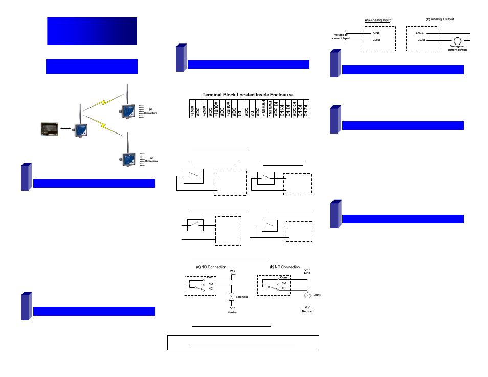
Power Supply Connections:
Connect the10-30 VDC power supply to the PWR IN
+/- terminals on the terminal blocks.
Digital Input Connections:
PWR IN +
DIx
(a) PNP (Sourcing) Input Wiring
with Internal Power Supply
DIx
(b) NPN (Sinking) Input Wiring
with Internal Power Supply
Com
+V
DIx
(c) PNP (Sourcing) Input Wiring with
External Power Supply
Com
Com
DIx
(d) NPN (Sinking) Input Wiring
with External Power Supply
Com
Com
Digital Output (Relay) Connections:
Analog Input & Output Connections:
Quick Start Guide
Zlinx™ Xtreme I/O
I
I
n
n
s
s
t
t
a
a
l
l
l
l
Z
Z
l
l
i
i
n
n
x
x
T
T
M
M
M
M
a
a
n
n
a
a
g
g
e
e
r
r
S
S
o
o
f
f
t
t
w
w
a
a
r
r
e
e
Insert the CD into your CD ROM Drive. The Zlinx™
Manager Install Wizard should start. Follow the on-screen
instructions to install the software.
3
If auto run is disabled, locate the ZlinxMgr.exe file on the
CD-ROM drive and double click to launch it. The Install
Wizard should start. Follow the on-screen instructions.
I
I
n
n
s
s
t
t
a
a
l
l
l
l
U
U
S
S
B
B
D
D
r
r
i
i
v
v
e
e
r
r
s
s
Connect the I/O module to the USB port on your PC.
5
The “Found New Hardware Wizard” will guide you through
the installation process.
When prompted to connect to Windows Updates to search for
drivers, select “No, not at this time” and follow the instructions
for installing from the CD or the location on the hard drive.
Choose the drivers manually from the CD or the location
where Zlinx™ Manager Software is installed.
When the driver is installed a new COM port labeled
“Xtreme” will show up in Windows Device Manager.
E
E
a
a
s
s
y
y
M
M
o
o
d
d
e
e
C
C
o
o
n
n
f
f
i
i
g
g
u
u
r
r
a
a
t
t
i
i
o
o
n
n
With power applied to the Zlinx Xtreme I/O module, press
and HOLD the Configuration Push Button on the inside
top lid until all the Mode LED’s on the front cover flash.
4
6
1
A single LED will flash depending on the current mode
Press the Push Button until the configuration mode
increments to Modbus mode. Modbus LED will be ON.
If the Push Button is not pressed for 4 sec, the device will
exit with Modbus mode selected.
The Zlinx Xtreme I/O module is now ready to communicate to
the Radio Modem in default mode.
2
Detailed setup changes can be done using the Zlinx
Manager Software using the following steps.
Refer to Zlinx Xtreme I/O manual for more details