Electrical characteristics (continued) – Rainbow Electronics MAX3799 User Manual
Page 5
MAX3799
1Gbps to 14Gbps, SFP+ Multirate Limiting
Amplifier and VCSEL Driver
_______________________________________________________________________________________
5
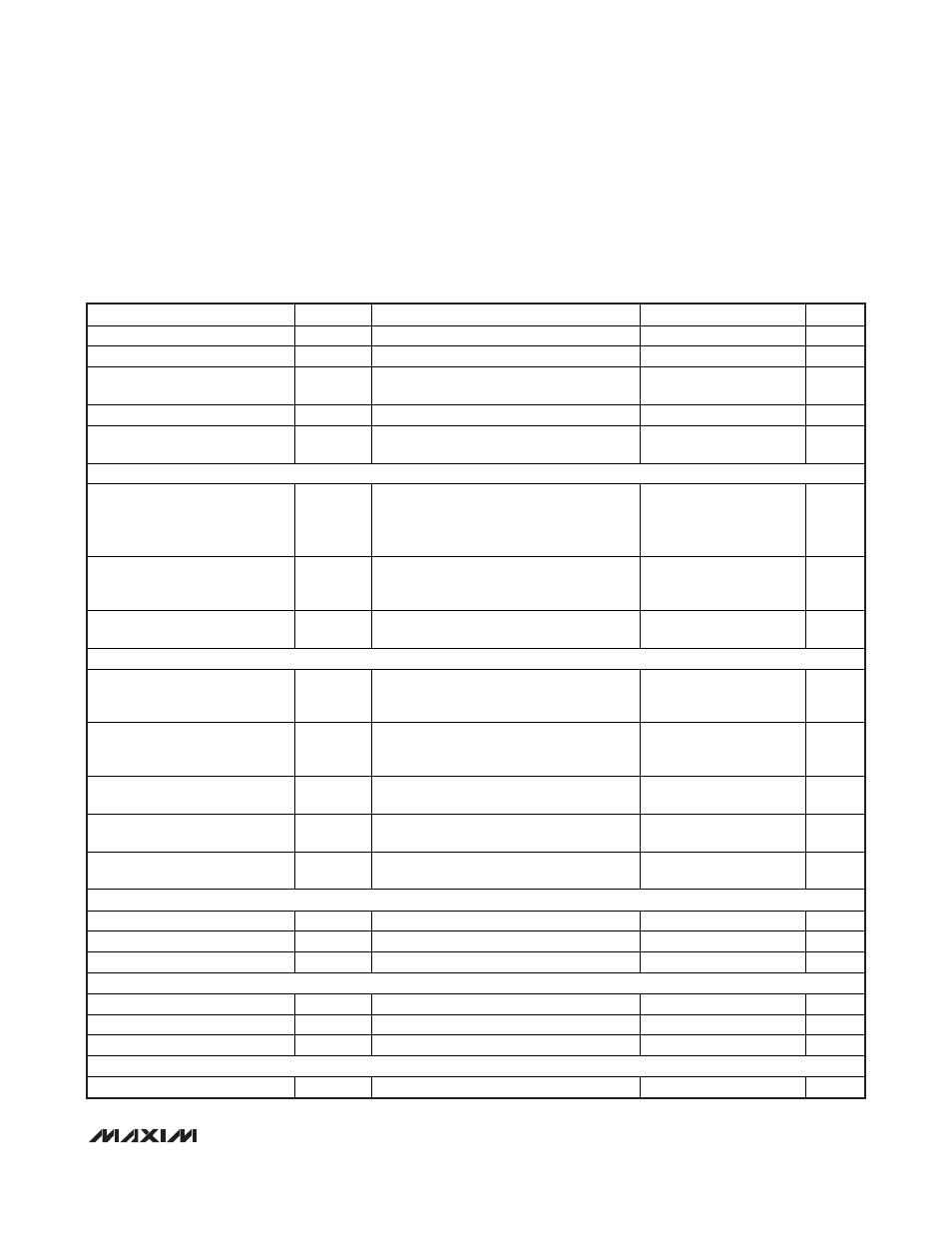
ELECTRICAL CHARACTERISTICS (continued)
(V
CC
= 2.85V to 3.63V, T
A
= -40°C to +85°C, CML receiver output load is AC-coupled to differential 100
Ω, C
AZ
= 1nF, transmitter out-
put load is AC-coupled to differential 100
Ω (see Figure 1), typical values are at +25°C, V
CC
= 3.3V, I
BIAS
= 6mA, I
MOD
= 6mA, unless
otherwise specified. Registers are set to default values unless otherwise noted, and the 3-wire interface is static during measure-
ments. For testing, the RATE_SEL bit was used and the RSEL pin was left open.)
PARAMETER SYMBOL
CONDITIONS
MIN
TYP
MAX
UNITS
BIAS Current DAC Stability
2mA
I
BIAS
15mA (Notes 2, 10)
4
%
Compliance Voltage at BIAS
V
BIAS
0.9
2.1
V
BIAS Current Monitor Current
Gain
I
BMON
External resistor to GND defines the
voltage gain
16
mA/A
Compliance Voltage at BMON
V
BMON
0
1.8
V
BIAS Current Monitor Current
Gain Stability
I
BMON
2mA
I
BIAS
15mA (Note 10)
5
%
Tx SAFETY FEATURES
Excessive Voltage at BMON
V
BMON
Average voltage, FAULT warning always
occurs for V
BMON
V
CC
- 0.55V, FAULT
warning never occurs for V
BMON
V
CC
-
0.65V
V
CC
-
0.65V
V
CC
-
0.6V
V
CC
-
0.55V
V
Excessive Voltage at BIAS
V
BIAS
Average voltage, FAULT always occurs for
V
BIAS
0.44V, FAULT never occurs for
V
BIAS
0.65V
0.44 0.48 0.65 V
Maximum VCSEL Current in Off
State
I
OFF
FAULT or DISABLE, V
BIAS
= V
CC
25
μA
SFP TIMING REQUIREMENTS
DISABLE Assert Time
t_
OFF
Time from rising edge of DISABLE input
signal to I
BIAS
= I
BIASOFF
and I
MOD
=
I
MODOFF
1
μs
DISABLE Negate Time
t_
ON
Time from falling edge of DISABLE to I
BIAS
and I
MOD
at 90% of steady state when
FAULT = 0 before reset
500
μs
FAULT Reset Time of Power-On
Time
t_
INIT
Time from power-on or negation of FAULT
using DISABLE
100
ms
FAULT Reset Time
t_
FAULT
Time from fault to FAULT on,
C
FAULT
20pF, R
FAULT
= 4.7k
10
μs
DISABLE to Reset
Time DISABLE must be held high to reset
FAULT
5 μs
OUTPUT_LEVEL VOLTAGE DAC (SET_CML)
Full-Scale Voltage
V
FS
100
differential resistive load
1200
mV
P-P
Resolution
5
mV
P-P
Integral Nonlinearity
INL
5mA
I
CML_LEVEL
20mA
±0.9
LSB
LOS THRESHOLD VOLTAGE DAC (SET_LOS)
Full-Scale Voltage
V
FS
94
mV
P-P
Resolution
1.5
mV
P-P
Integral Nonlinearity
INL
11mV
P-P
V
TH_LOS
94mV
P-P
±0.7
LSB
BIAS CURRENT DAC (SET_IBIAS)
Full-Scale Current
I
FS
21
mA