Table 5. register descriptions and addresses – Rainbow Electronics MAX3799 User Manual
Page 21
MAX3799
1Gbps to 14Gbps, SFP+ Multirate Limiting
Amplifier and VCSEL Driver
______________________________________________________________________________________
21
ADDRESS NAME
FUNCTION
H0x00
RXCTRL1
Receiver Control Register 1
H0x01
RXCTRL2
Receiver Control Register 2
H0x02 RXSTAT
Receiver
Status
Register
H0x03
SET_CML
Output CML Level Setting Register
H0x04
SET_LOS
LOS Threshold Level Setting Register
H0x05 TXCTRL
Transmitter
Control
Register
H0x06 TXSTAT1
Transmitter
Status
Register
1
H0x07 TXSTAT2
Transmitter
Status
Register
2
H0x08
SET_IBIAS
Bias Current Setting Register
H0x09
SET_IMOD
Modulation Current Setting Register
H0x0A
IMODMAX
Maximum Modulation Current Setting Register
H0x0B
IBIASMAX
Maximum Bias Current Setting Register
H0x0C
MODINC
Modulation Current Increment Setting Register
H0x0D
BIASINC
Bias Current Increment Setting Register
H0x0E MODECTRL
Mode
Control
Register
H0x0F SET_PWCTRL
Transmitter
Pulse-Width
Control
Register
H0x10
SET_TXDE
Transmitter Deemphasis Control Register
Table 5. Register Descriptions and Addresses
CSEL
SCL
SDA
CSEL
SCL
SDA
1
2
3
4
5
6
7
8
A6
9
10
11
12
13
14
15
0
1
2
3
4
5
6
7
8
9
10
11
12
13
14
15
0
A5
A4
A3
A2
A1
RWN
D7
D6
D5
D4
D3
D2
D1
D0
D7
D6
D5
D4
D3
D2
D1
D0
RWN
WRITE MODE
READ MODE
A0
A6
A5
A4
A3
A2
A1
A0
t
L
t
L
t
CH
t
CL
t
DS
t
DH
t
CH
t
CL
t
DS
t
D
t
DH
t
T
t
T
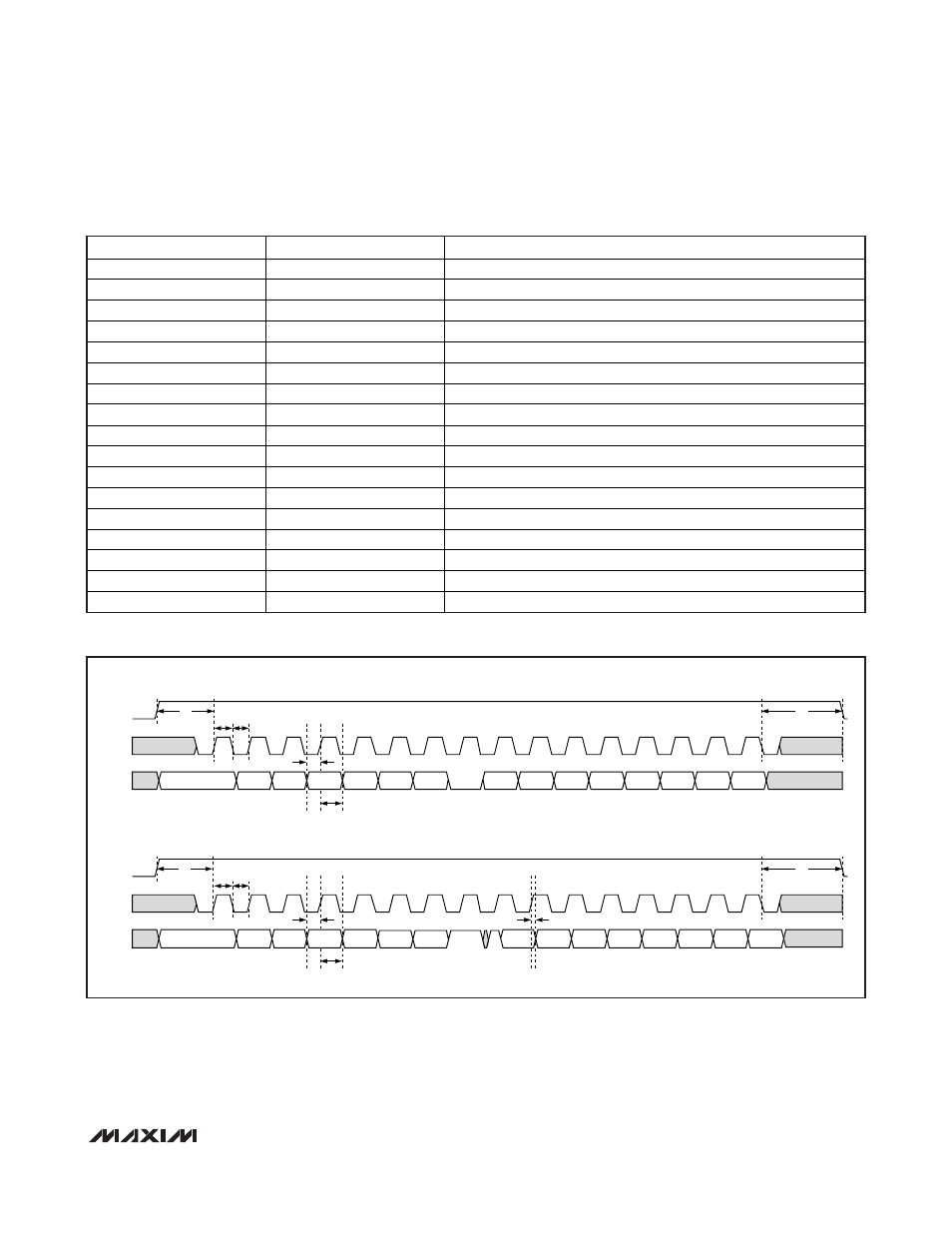
Figure 4. Timing for 3-Wire Digital Interface