Max3799 – Rainbow Electronics MAX3799 User Manual
Page 22
MAX3799
Register Descriptions
Receiver Control Register 1 (RXCTRL1)
Bit 1: RATE_SEL. RATE_SEL combined with the RSEL pin through a logic-OR function selects between the low
data-rate mode (1.25Gbps) or high data-rate mode (up to 10.32Gbps).
Logic-OR output 0 = 1Gbps mode
Logic-OR output 1 = 10Gbps mode
Receiver Control Register 2 (RXCTRL2)
Bit 6: LOS_EN. Controls the LOS circuitry. When RX_EN is set to 0, the LOS detector is also disabled.
0 = disabled
1 = enabled
Bit 5: LOS_POL. Controls the output polarity of the LOS pin.
0 = inverse
1 = normal
Bit 4: RX_POL. Controls the polarity of the receiver signal path.
0 = inverse
1 = normal
Bit 3: SQ_EN. When SQ_EN = 1, the LOS controls the output circuitry.
0 = disabled
1 = enabled
Bit 2: RX_EN. Enables or disables the receive circuitry.
0 = disabled
1 = enabled
Bit 1: RXDE_EN. Enables or disables the deemphasis on the receiver output.
0 = disabled
1 = enabled
Bit 0: AZ_EN. Enables or disables the autozero circuitry. When RX_EN is set to 0, the autozero circuitry is also disabled.
0 = disabled
1 = enabled
1Gbps to 14Gbps, SFP+ Multirate Limiting
Amplifier and VCSEL Driver
22
______________________________________________________________________________________
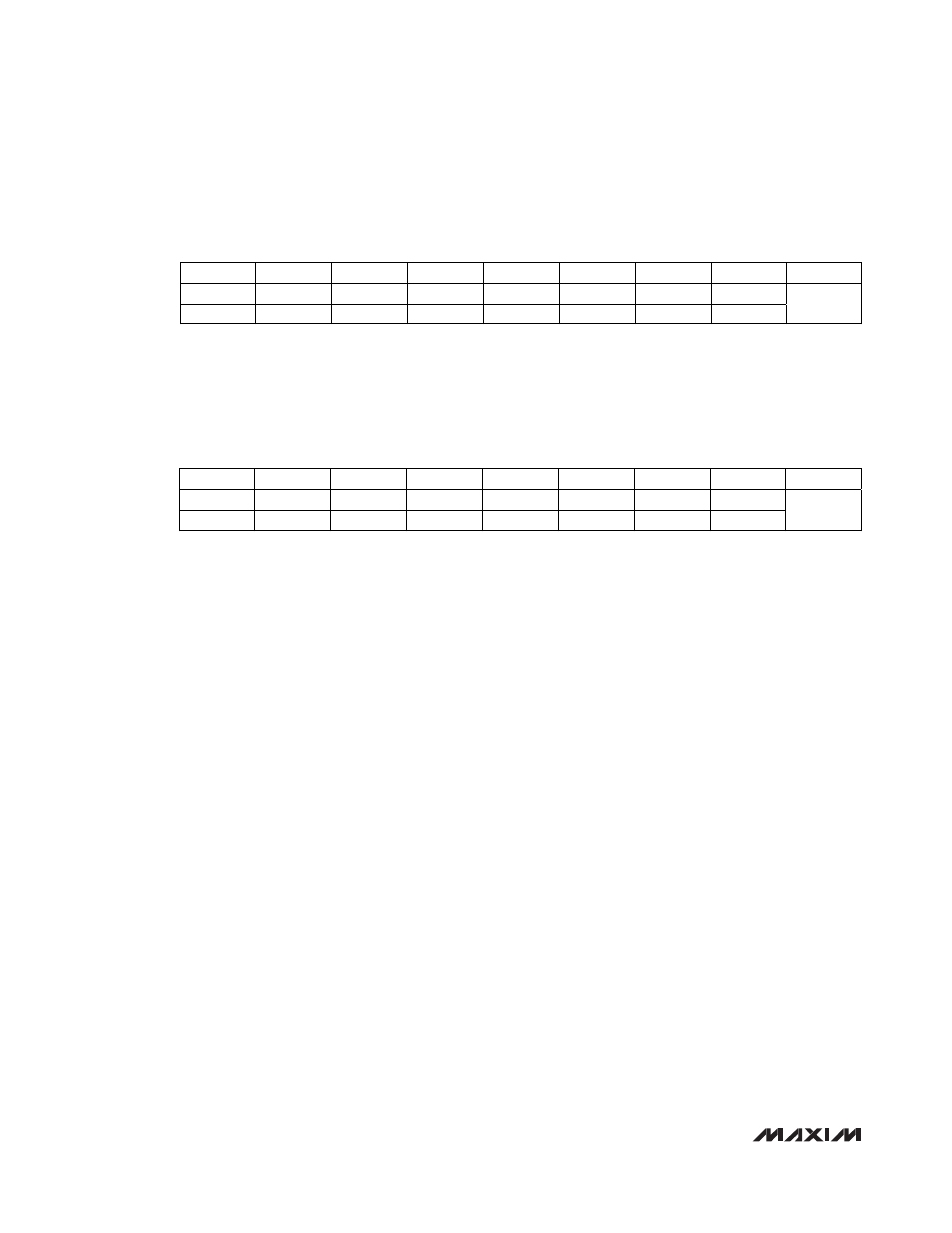
Bit #
7 6 5 4 3 2 1 0
ADDRESS
Name
X X X X X X
RATE_SEL
X
Default
Value
X X X X X X 0 X
H0x00
Bit #
7 6 5 4 3 2 1 0
ADDRESS
Name X
LOS_EN
LOS_POL
RX_POL
SQ_EN
RX_EN
RXDE_EN
AZ_EN
Default
Value
X 1 1 1 0 1 0 1
H0x01