Rainbow Electronics MAX3799 User Manual
Page 11
MAX3799
1Gbps to 14Gbps, SFP+ Multirate Limiting
Amplifier and VCSEL Driver
______________________________________________________________________________________
11
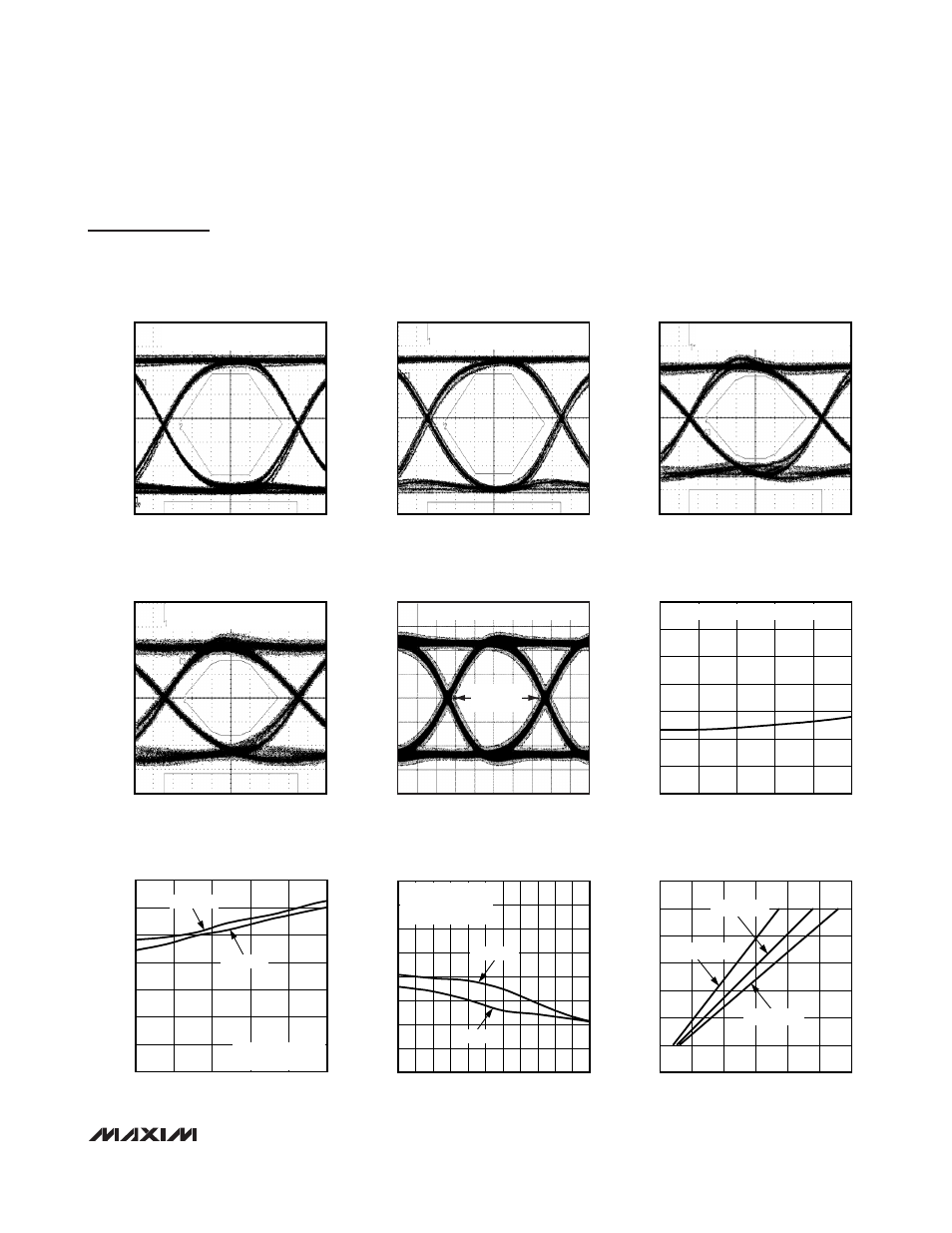
Typical Operating Characteristics—VCSEL Driver (continued)
(V
CC
= 3.3V, T
A
= +25°C, unless otherwise specified. Figure 1 shows the typical setup used for measurements. Registers are set to
default values unless otherwise noted, and the 3-wire interface is static during measurements. For testing, the RATE_SEL bit was
used and the RSEL pin was left open.)
OPTICAL EYE DIAGRAM
MAX3799 toc19
68ps/div
2.125Gbps, SET_IMOD = 60, 2
7
- 1 PRBS,
850nm VCSEL, MASK WITH 50%
OPTICAL EYE DIAGRAM
MAX3799 toc20
34ps/div
4.25Gbps, SET_IMOD = 60, 2
7
- 1 PRBS,
850nm VCSEL, MASK WITH 46%
OPTICAL EYE DIAGRAM
MAX3799 toc21
17ps/div
8.5Gbps, SET_IMOD = 60, 2
7
- 1 PRBS,
850nm VCSEL, MASK WITH 54%
OPTICAL EYE DIAGRAM
MAX3799 toc22
14ps/div
10.3Gbps, SET_IMOD = 60, 2
7
- 1 PRBS,
850nm VCSEL, MASK WITH 44%
ELECTRICAL EYE DIAGRAM
MAX3799 toc23
14ps/div
14.025Gbps, SET_IMOD = 60, 2
31
- 1 PRBS
EYE WIDTH
62.8ps
DETERMINISTIC JITTER
vs. MODULATION CURRENT
MAX3799 toc24
MODULATION CURRENT (mA
P-P
)
DETERMINISTIC JITTER (ps)
10
8
6
4
5.0
5.5
6.0
6.5
7.0
7.5
8.0
4.5
2
12
PATTERN = PRBS, DATA RATE = 10.32Gbps
TRANSITION TIME
vs. MODULATION CURRENT
MAX3799 toc25
MODULATION CURRENT (mA
P-P
)
TRANSITION TIME (ps)
10
8
6
4
8
13
18
23
28
33
38
3
2
12
FALL TIME
RISE TIME
PATTERN = 11110000,
DATA RATE = 8.5Gbps
TRANSITION TIME
vs. DEEMPHASIS SETTING
MAX3799 toc26
SET_TXDE[3:0]
TRANSITION TIME (ps)
10
9
1
2
3
5
6
7
4
8
27
29
31
33
35
37
39
41
25
0
11
FALL TIME
RISE TIME
PATTERN = 11110000,
DATA RATE = 8.5Gbps,
I
MOD
= 10mA
P-P
MODULATION CURRENT
vs. DAC SETTING
MAX3799 toc27
SET_IMOD[8:0]
MODULATION CURRENT (mA)
250
200
150
100
50
2
4
6
8
10
12
14
0
0
300
R
LOAD
= 50
Ω
R
LOAD
= 75
Ω
R
LOAD
= 100
Ω