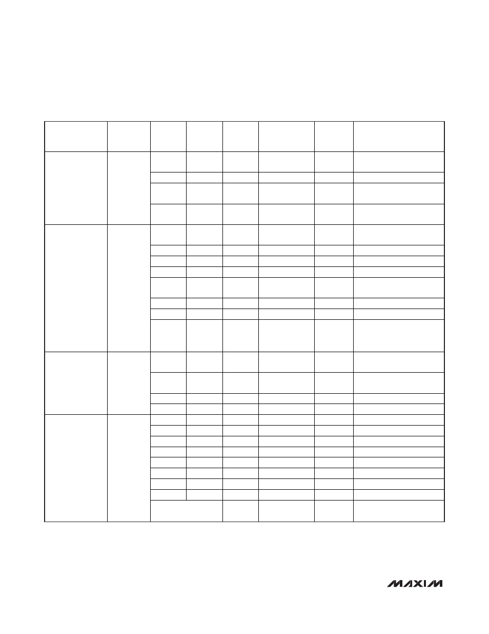
Table 7. register summary (continued) – Rainbow Electronics MAX3799 User Manual
Page 30
MAX3799
1Gbps to 14Gbps, SFP+ Multirate Limiting
Amplifier and VCSEL Driver
30
______________________________________________________________________________________
REGISTER
FUNCTION/
ADDRESS
REGISTER
NAME
NORMAL
MODE
SETUP
MODE
BIT
NUMBER
/TYPE
BIT NAME
DEFAULT
VALUE
NOTES
R RW 3 TXDE_EN 0
Tx deemphasis
0: disable, 1: enable
R
RW
2
SOFTRES
0
Global digital reset
R RW 1 TX_POL 1
Tx polarity
0: inverse, 1: normal
Transmitter
Control Register
Address = H0x05
TXCTRL
R RW 0 TX_EN
1
Tx control
0: disable, 1: enable
R R
7
(sticky)
FST[7] X
TX_POR
TX_VCC low-
limit violation
R
R
6 (sticky)
FST[6]
X
BMON open/shorted to V
CC
R R
5
(sticky) X
X
R R
4
(sticky) X
X
R R
3
(sticky)
FST3] X
V
TOUT
+/- common-mode
low-limit violation
R R
2
(sticky)
FST[2] X
V
TOUT
+/- low-limit violation
R
R
1 (sticky)
FST[1]
X
BIAS open or shorted to GND
Transmitter Status
Register 1
Address = H0x06
TXSTAT1
R R
0
(sticky)
TX_FAULT X
Copy of FAULT signal in
case POR bits 6 to 1 reset
to 0
R R
3
(sticky)
IMODERR X
Warning increment result >
IMODMAX
R R
2
(sticky)
IBIASERR X
Warning increment result >
IBIASMAX
R R
1
(sticky)
TXED X
Tx
edge
detection
Transmitter Status
Register 2
Address = H0x07
TXSTAT2
R R
0
(sticky)
Unused X
Unused
R
RW
8
SET_IBIAS[8]
0
MSB bias DAC
R RW 7
SET_IBIAS[7]
0
R RW 6
SET_IBIAS[6]
0
R RW 5
SET_IBIAS[5]
0
R RW 4
SET_IBIAS[4]
0
R RW 3
SET_IBIAS[3]
1
R RW 2
SET_IBIAS[2]
0
R RW 1
SET_IBIAS[1]
0
Bias Current
Setting Register
Address = H0x08
SET_IBIAS
Accessible through
REG_ADDR = 13
0
SET_IBIAS[0]
0
LSB bias DAC
Table 7. Register Summary (continued)