Max109, Static/dc parameter definitions, Dynamic/ac parameter definitions – Rainbow Electronics MAX109 User Manual
Page 26: Integral nonlinearity (inl), Differential nonlinearity (dnl), Offset error, Bit error rates, Signal-to-noise ratio (snr), Signal-to-noise plus distortion (sinad)
MAX109
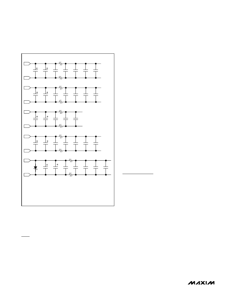
supply for the chip should have its own 0.01µF capaci-
tor, which should be placed as close as possible to the
MAX109 for optimum high-frequency noise filtering.
Static/DC Parameter Definitions
Integral Nonlinearity (INL)
Integral nonlinearity is the deviation of the values on an
actual transfer function from a straight line. For the
MAX109, this straight line is between the endpoints of
the transfer function, once offset and gain errors have
been nullified. INL deviations are measured at every
step of the transfer function and the worst-case devia-
tion is reported in the
Electrical Characteristics
table.
Differential Nonlinearity (DNL)
Differential nonlinearity is the difference between an
actual step width and the ideal value of 1 LSB. A DNL
error specification of less than 1 LSB guarantees no
missing codes and a monotonic transfer function. For
the MAX109, DNL deviations are measured at every
step of the transfer function and the worst-case devia-
tion is reported in the
Electrical Characteristics
table.
Offset Error
Offset error is a figure of merit that indicates how well
the actual transfer function matches the ideal transfer
function at a single point. Ideally, the mid-scale
MAX109 transition occurs at 0.5 LSB above mid scale.
The offset error is the amount of deviation between the
measured mid-scale transition point and the ideal mid-
scale transition point.
Bit Error Rates
Errors resulting from metastable states may occur when
the analog input voltage (at the time the sample is
taken) falls close to the decision point of any one of the
input comparators. Here, the magnitude of the error
depends on the location of the comparator in the com-
parator network. If it is the comparator for the MSB, the
error will reach full scale. The MAX109’s unique encod-
ing scheme solves this problem by limiting the magni-
tude of these errors to 1 LSB.
Dynamic/AC Parameter
Definitions
Signal-to-Noise Ratio (SNR)
For a waveform perfectly reconstructed from digital
samples, the theoretical maximum SNR is the ratio of
the full-scale analog input (RMS value) to the RMS
quantization error (residual error). The ideal theoretical
minimum analog-to-digital noise is caused by quantiza-
tion error only and results directly from the ADC’s reso-
lution (N bits):
SNR[max] = 6.02 x N + 1.76
In reality, there are other noise sources besides quanti-
zation noise: thermal noise, reference noise, clock jitter,
etc. SNR is computed by taking the ratio of the RMS
signal to the RMS noise. RMS noise includes all spec-
tral components to the Nyquist frequency excluding the
fundamental, the first 15 harmonics (HD2 through
HD16), and the DC offset:
SNR = 20 x log (SIGNAL
RMS
/ NOISE
RMS
)
Signal-to-Noise Plus Distortion (SINAD)
SINAD is computed by taking the ratio of the RMS sig-
nal to the RMS noise plus distortion. RMS noise plus
8-Bit, 2.2Gsps ADC with Track/Hold Amplifier
and 1:4 Demultiplexed LVDS Outputs
26
______________________________________________________________________________________
330µF
GNDD
V
CC
D
GNDA
V
CC
A
GNDI
V
CC
I
GNDI
1N5817
V
EE
V
CC
A = +4.75V TO +5.25V
V
CC
D = +4.75V TO +5.25V
V
CC
I = +4.75V TO +5.25V
V
CC
O = +3.0V TO V
CC
D
V
EE
= -4.75V TO -5.25V
NOTE:
LOCATE ALL 0.01µF CAPACITORS AS CLOSE AS POSSIBLE TO THE MAX109 DEVICE.
GNDD
V
CC
O
33µF
0.1µF
0.01µF
0.01µF
0.01µF
0.01µF
330µF
33µF
0.1µF
330µF
33µF
0.1µF
0.01µF
0.01µF
0.01µF
0.01µF
330µF
33µF
0.1µF
0.01µF
0.01µF
0.01µF
0.01µF
0.01µF
0.01µF
0.01µF
0.01µF
0.01µF
0.01µF
330µF
33µF
0.1µF
Figure 17. MAX109 Decoupling and Bypassing
Recommendations