Max109, Pin description – Rainbow Electronics MAX109 User Manual
Page 12
MAX109
8-Bit, 2.2Gsps ADC with Track/Hold Amplifier
and 1:4 Demultiplexed LVDS Outputs
12
______________________________________________________________________________________
PIN
NAME
12
______________________________________________________________________________________
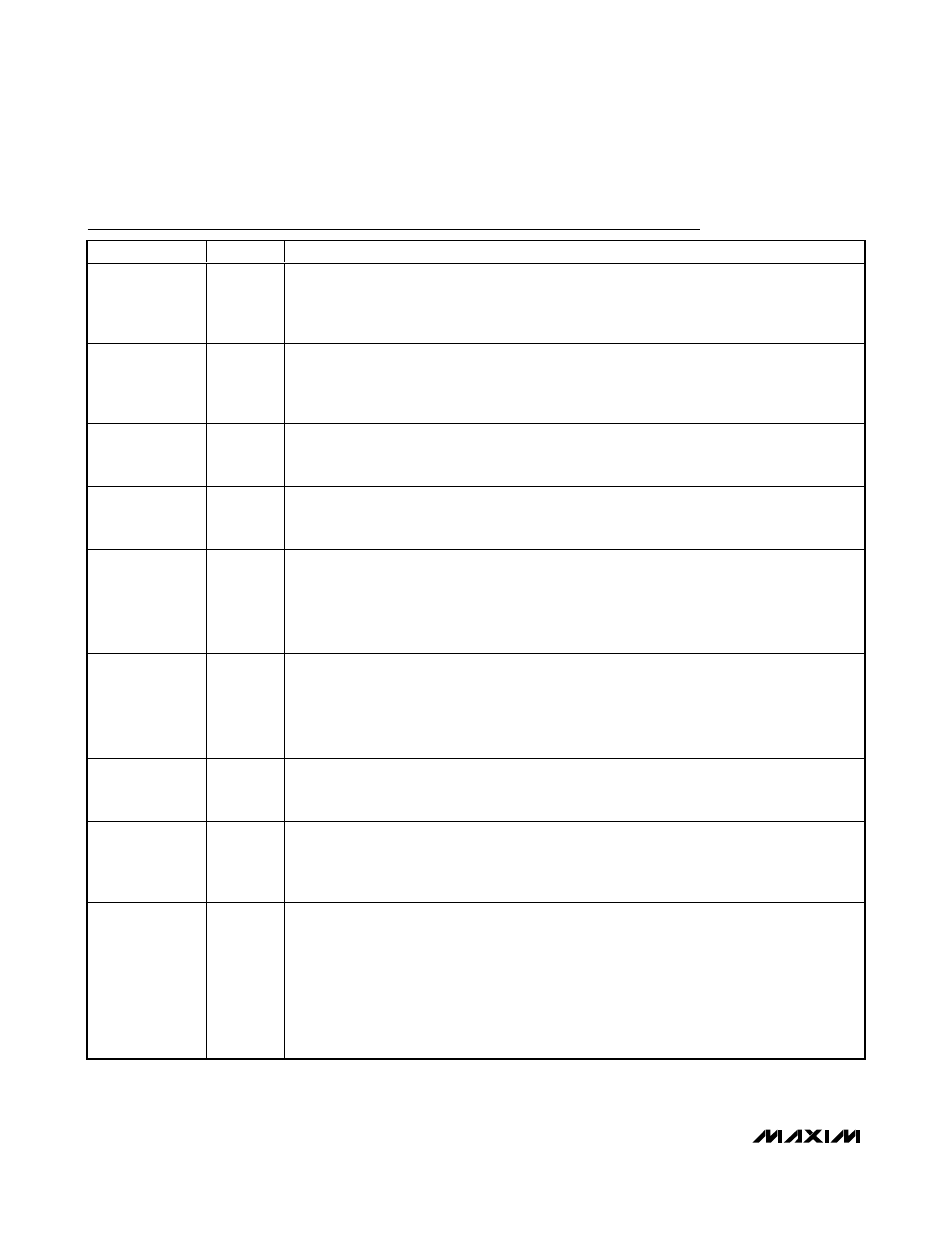
Pin Description
PIN
NAME
FUNCTION
A1, A2, B1, B2,
C1–C5, D5,
L1–L4, U5, V1–V4,
W1, W2, Y1, Y2
V
CC
O
LVDS Output Power Supply. Accepts an input-voltage range of 3.3V ±10%.
A3, A4, B3, B4,
D1–D4, K1–K4,
U1–U4, W3, W4,
Y3, Y4
GNDO
LVDS Output Ground. Ground connection for LVDS output drivers.
A9, B9, C10, D10,
U10, V10, W10,
Y10
V
CC
D
Digital Logic Power Supply. Accepts an input-voltage range of 5V ±5%.
A10, B10, C11,
D11, U11, V11,
W11, Y11
GNDD
Digital Ground. Ground connection for digital logic circuitry.
A11, A19, B11,
B18, C12, C18,
D12, D18, E17,
U17, V17, W17,
Y17, U12, V12,
W12, Y12
V
CC
A
Analog Supply Voltage for Comparator Array. Accepts an input-voltage range of 5V ±5%.
A12, A18, B12,
B13, B17, C13,
C17, D13, D17,
U13, U16, V13,
V16, W13, W16,
Y13, Y16
GNDA
Analog Ground. Ground connection for comparator array.
H17–H20,
P17–P20, U15,
V15, W15, Y15
V
CC
I
Analog Supply Voltage. Analog power supply (positive rail) for T/H amplifier. Accepts an input-
voltage range of 5V ±5%.
E18, F17–F20,
J17, J18, J19,
N17, N18, N19,
T17–T20, U18
V
EE
Negative Power Supply. Analog power supply (negative rail) for the T/H amplifier. Accepts an
input-voltage range of -5V ±5%.
D 19, D 20, E 19,
E 20, G17–G20,
J20, K17, K18,
K19, L17–L20,
M 17, M 18, M 19,
N 20, R17–R20,
U 14, U 19, U 20,
V 14, V 19, V 20,
W14, Y 14
GNDI
Analog Ground. Ground connection for the T/H amplifier.