Max109, Table 3. pseudorandom number generator patterns – Rainbow Electronics MAX109 User Manual
Page 19
(double data rate), and QDR (quadruple data rate).
Setting these two bits for different modes allows the
user to update and process the outputs at one-quarter
(SDR mode), one-eighth (DDR mode), or one-sixteenth
(QDR mode) the sampling clock (Table 2), relaxing the
need for an ultra-fast FPGA or data-capture interface.
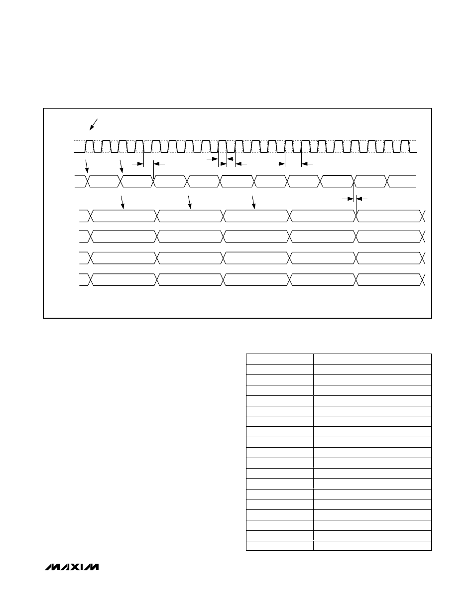
Data is presented on all four ports of the converter-
demultiplexer circuit outputs. Note that there is a data
latency between the sampled data and each of the out-
put ports. The data latency is 10.5 clock cycles for
PortA, 9.5 clock cycles for PortB, 8.5 clock cycles for
PortC, and 7.5 clock cycles for PortD. This holds true for
all demultiplexer modes. Figures 6, 7, and 8 display the
demultiplexer timing for f
CLK
/ 4, f
CLK
/ 8, and f
CLK
/ 16
modes.
Pseudorandom Number (PRN) Generator
The MAX109 features a PRN generator that enables the
user to test the demultiplexed digital outputs at full
clock speed and with a known test pattern. The PRN
generator is a combination of shift register and feed-
back logic with 255 states. When PRN is high, the inter-
MAX109
8-Bit, 2.2Gsps ADC with Track/Hold Amplifier
and 1:4 Demultiplexed LVDS Outputs
______________________________________________________________________________________
19
Table 3. Pseudorandom Number
Generator Patterns
CODE
OUTPUT PRN PATTERN
1
0 0 0 0 0 0 0 1
2
0 0 0 0 0 0 1 0
3
0 0 0 0 0 1 0 0
4
0 0 0 0 1 0 0 0
5
0 0 0 1 0 0 0 1
6
0 0 1 0 0 0 1 1
7
0 1 0 0 0 1 1 1
8
1 0 0 0 1 1 1 0
9
0 0 0 1 1 1 0 0
10
0 0 1 1 1 0 0 0
—
—
—
—
250
0 0 1 1 0 1 0 0
251
0 1 1 0 1 0 0 0
252
1 1 0 1 0 0 0 0
253
1 0 1 0 0 0 0 0
254
0 1 0 0 0 0 0 0
255
1 0 0 0 0 0 0 0
CLKN
CLKP
N
N + 1
N + 2
N + 3
N + 4
N + 5
N + 4
N
N + 6
N + 3
N + 5
N + 8
N + 7
N + 1
N + 2
N + 6
N + 7
N + 8
N + 9 N + 10 N + 11 N + 12 N + 13 N + 14 N + 15 N + 16 N + 17 N + 18 N + 19
ADC SAMPLE NUMBER
ADC SAMPLES ON THE RISING EDGE OF CLKP
t
PWH
t
PWL
t
CLK
t
PD2
t
PD1
DCON
DCOP
PORTA DATA
PORTB DATA
NOTE: THE LATENCY TO THE D PORT IS 7.5 CLOCK CYCLES, THE LATENCY TO THE C PORT IS 8.5 CLOCK CYCLES, THE LATENCY TO THE B
PORT IS 9.5 CLOCK CYCLES, AND THE LATENCY TO THE A PORT IS 10.5 CLOCK CYCLES. ALL DATA PORTS (PORTA, PORTB, PORTC, AND
PORTD) ARE UPDATED ON THE RISING EDGE OF THE DCOP CLOCK.
PORTC DATA
PORTD DATA
SAMPLE HERE
Figure 6. Timing Diagram for SDR Mode, fCLK / 4 Mode