Definitions, Layout, grounding, and bypassing, Integral nonlinearity – Rainbow Electronics MAX1383 User Manual
Page 18: Differential nonlinearity, Aperture jitter, Aperture delay
MAX1377/MAX1379/MAX1383
Dual, 12-Bit, 1.25Msps Simultaneous-Sampling
ADCs with Serial Interface
18
______________________________________________________________________________________
Layout, Grounding, and Bypassing
For best performance, use PCBs with ground planes.
Ensure that digital and analog signal lines are separat-
ed from each other. Do not run analog and digital
(especially clock) lines parallel to one another or digital
lines underneath the ADC package.
Establish a single-point analog ground (star ground point)
at AGND, separate from the digital ground, DGND.
Connect all other analog grounds and DGND to this star
ground point for further noise reduction. The ground return
to the power supply for this ground should be low imped-
ance and as short as possible for noise-free operation.
See Figure 14.
High-frequency noise in the AVDD power supply affects
the ADC’s high-speed comparator. Bypass the supply
to the single-point analog ground with 0.01µF and 10µF
bypass capacitors. Minimize capacitor lead lengths for
best supply-noise rejection.
Definitions
Integral Nonlinearity
Integral nonlinearity (INL) is the deviation of the values
on an actual transfer function from a straight line. This
straight line can be either a best-straight-line fit or a line
drawn between the end points of the transfer function,
once offset and gain errors have been nulled. The static
linearity parameters for the MAX1377/MAX1379/
MAX1383 are measured using the end-points method.
Differential Nonlinearity
Differential nonlinearity (DNL) is the difference between
an actual step width and the ideal value of 1 LSB. A
DNL error specification of 1 LSB or less guarantees no
missing codes and a monotonic transfer function.
Aperture Jitter
Aperture jitter (t
AJ
) is the sample-to-sample variation in
the time between the samples.
Aperture Delay
Aperture delay (t
AD
) is the time defined between the
falling edge of CNVST and the instant when an actual
sample is taken.
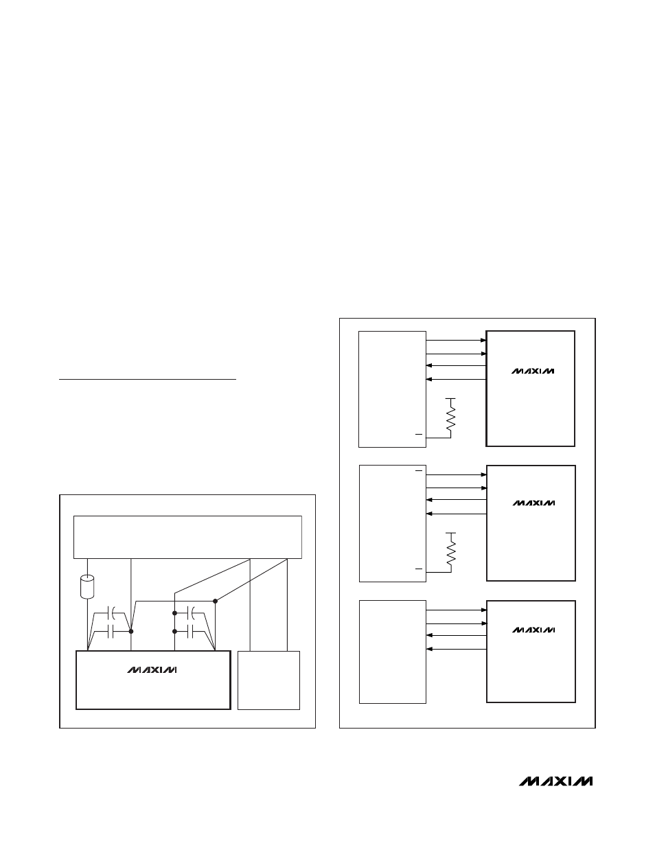
MAX1377
MAX1379
MAX1383
I/O
SCK
MISO1
MISO2
SS
3V TO 5V
CNVST
SCLK
DOUT1
DOUT2
MAX1377
MAX1379
MAX1383
SCK
MISO1
MISO2
SS
3V TO 5V
CNVST
SCLK
DOUT1
DOUT2
MAX1377
MAX1379
MAX1383
I/O
SK
SI1
SI2
CNVST
SCLK
DOUT1
DOUT2
A) SPI
B) QSPI
C) MICROWIRE
CS
Figure 15. Common Serial-Interface Connections to the
MAX1377/MAX1379/MAX1383
SUPPLIES
AVDD
AGND
DGND
V
DD
DIGITAL
CIRCUITRY
OPTIONAL
FERRITE
BEAD
ANALOG
SUPPLY
RETURN
RETURN
DIGITAL
SUPPLY
V
L
GND
MAX1377
MAX1379
MAX1383
Figure 14. Power-Supply Grounding and Bypassing