Applications information, Spi and microwire, Qspi – Rainbow Electronics MAX1383 User Manual
Page 17: Three-phase motor controller, Wireless communication
MAX1377/MAX1379/MAX1383
Dual, 12-Bit, 1.25Msps Simultaneous-Sampling
ADCs with Serial Interface
______________________________________________________________________________________
17
Applications Information
SPI and MICROWIRE
The MAX1377/MAX1379/MAX1383 are compatible with
all four modes programmed with the CPHA and CPOL
bits in the SPI or MICROWIRE control register.
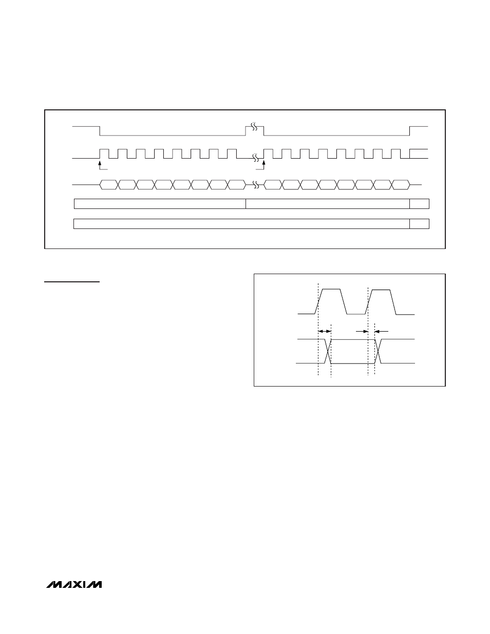
Conversion begins with a CNVST falling edge. DOUT_
goes low, indicating a conversion is in progress. Two
consecutive 8-bit reads are required to get the full 12
bits from the ADC. DOUT_ transitions on the rising edge
of SCLK. DOUT_ is guaranteed to be valid t
DOUT
after
the rising edge of SCLK and remains valid until t
DHOLD
after the next SCLK rising edge (see Figure 13).
For CPOL = 0 and CPHA = 0 or CPOL = 1 and CPHA =
1, the data is clocked into the µC on the rising edge of
SCLK. For CPOL = 0 and CPHA = 1 or CPOL = 1 and
CPHA = 0, the data is clocked into the µC on the falling
edge of SCLK. The MAX1377/MAX1379/MAX1383 are
compatible with all CPOL/CPHA configurations since
the data is valid on the falling and rising edge of SCLK.
QSPI
Unlike SPI, which requires two 8-bit reads to acquire
the 12 bits of data from the ADC, QSPI allows the mini-
mum number of clock cycles necessary to clock in the
data. The MAX1377/MAX1379/MAX1383 require 16
clock cycles from the µC to clock out the 12 bits of
data. The conversion result contains three zeros fol-
lowed by the 12 data bits, and a trailing zero with the
data in the MSB-first format.
Three-Phase Motor Controller
The MAX1377/MAX1379/MAX1383 are ideally suited for
motor-control systems (Figure 16). The devices’ simulta-
neously sampled inputs eliminate the need for complicat-
ed DSP algorithms that realign sequentially sampled
data into a simultaneous sample set. The ±10V
(MAX1383) input allows for standard industrial inputs,
eliminating the need for voltage-scaling amplifiers.
Wireless Communication
Use the MAX1377/MAX1379/MAX1383 in a variety of
wireless communication systems. These devices allow
precise, simultaneous sampling of the I and Q signals
of quadrature RF receiver systems. Figure 17 shows the
MAX1377 in a simplified quadrature system. The device
has a differential input option that allows either full dif-
ferential or psuedo-differential signals. The 2:1 input
mux allows measurement of RSSI and other system-
monitoring functions with this device.
1ST SCLK RISING EDGE
1ST SCLK RISING EDGE
0
D11
D10
D8
D7
DOUT_
MODE
SCLK
CNVST
0
0
FPD
PPD
NORMAL
0
DOUT_ ENTERS THREE-STATE ONCE CNVST GOES HIGH
EXECUTE PARTIAL POWER-DOWN SEQUENCE TWICE
0
0
0
0
0
D9
0
0
REF
ENABLED
DISABLED
Figure 12. Full Power-Down Mode Timing Sequence
SCLK
DOUT_
t
DHOLD
t
DOUT
Figure 13. Data Valid and Hold Times