Exiting partial and full power-down modes – Rainbow Electronics MAX1383 User Manual
Page 16
MAX1377/MAX1379/MAX1383
Dual, 12-Bit, 1.25Msps Simultaneous-Sampling
ADCs with Serial Interface
16
______________________________________________________________________________________
CNVST/SCLK sequence necessary to enter partial
power-down mode. Repeat the same sequence to enter
full power-down mode. In full power-down mode, the
internal reference is disabled to minimize power con-
sumption. Figure 12 shows the timing sequence to
enter full power-down mode.
Another way to enter the full power-down mode is to
drive
CS high. If CS is high, the MAX1377/MAX1379/
MAX1383 act as if the full power-down sequence were
issued. To exit the
CS-initiated power-down mode,
drive
CS low. Allow 2ms for the reference to wake up
and settle before performing a conversion.
Exiting Partial and Full Power-Down Modes
Drive CNVST low and allow at least 14 SCLK cycles to
elapse before driving CNVST high to exit partial or full
power-down mode. When exiting partial power-down
mode, conversions can begin immediately without hav-
ing to wait for the reference to wake-up. When exiting
full power-down mode, allow at least 2ms recovery time
after exiting to ensure that the internal reference has
settled.
In partial or full power-down mode, maintain idle SCLK
low or high to minimize power.
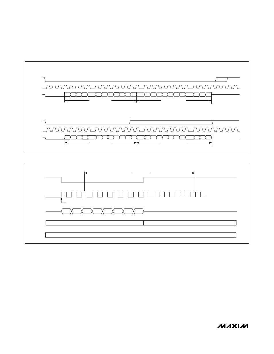
SINGLE CONVERSION
(SINGLE OUTPUT)
CNVST
SCLK
DOUT1
1
8
9
16
17
24
28
CONTINUOUS CONVERSION
(SINGLE OUTPUT)
CNVST
SCLK
DOUT1
1
8
9
16
14
17
24
25
28
27
D11 D10 D9 D8
D7
D6
D5 D4 D3 D2 D1 D0
D11 D10 D9 D8
D7 D6
D5 D4
D3
D2 D1 D0
D11 D10 D9 D8
D7
D6
D5 D4 D3 D2 D1 D0
D11 D10 D9 D8
D7 D6
D5 D4
D3
D2 D1 D0
CHANNEL 1
CONVERSION RESULT
CHANNEL 2
CONVERSION RESULT
HIGH-Z
CHANNEL 1
CONVERSION RESULT
CHANNEL 2
CONVERSION RESULT
0
0
0
0
0
0
Figure 10. Single-Output Mode, Single and Continuous Conversions
DOUT_
MODE
SCLK
CNVST
DOUT_ GOES HIGH IMPEDANCE ONCE CNVST GOES HIGH
CNVST MUST GO HIGH AFTER THE 3RD
BUT BEFORE THE 14TH
SCLK RISING EDGE
1ST SCLK RISING EDGE
PARTIAL POWER-DOWN
0
D11
D10
D9
D8
D7
NORMAL
0
0
REF
ENABLED
1
3
9
14
PPD WINDOW
Figure 11. Partial Power-Down Timing Sequence