Rainbow Electronics MAX1383 User Manual
Page 14
MAX1377/MAX1379/MAX1383
Dual, 12-Bit, 1.25Msps Simultaneous-Sampling
ADCs with Serial Interface
14
______________________________________________________________________________________
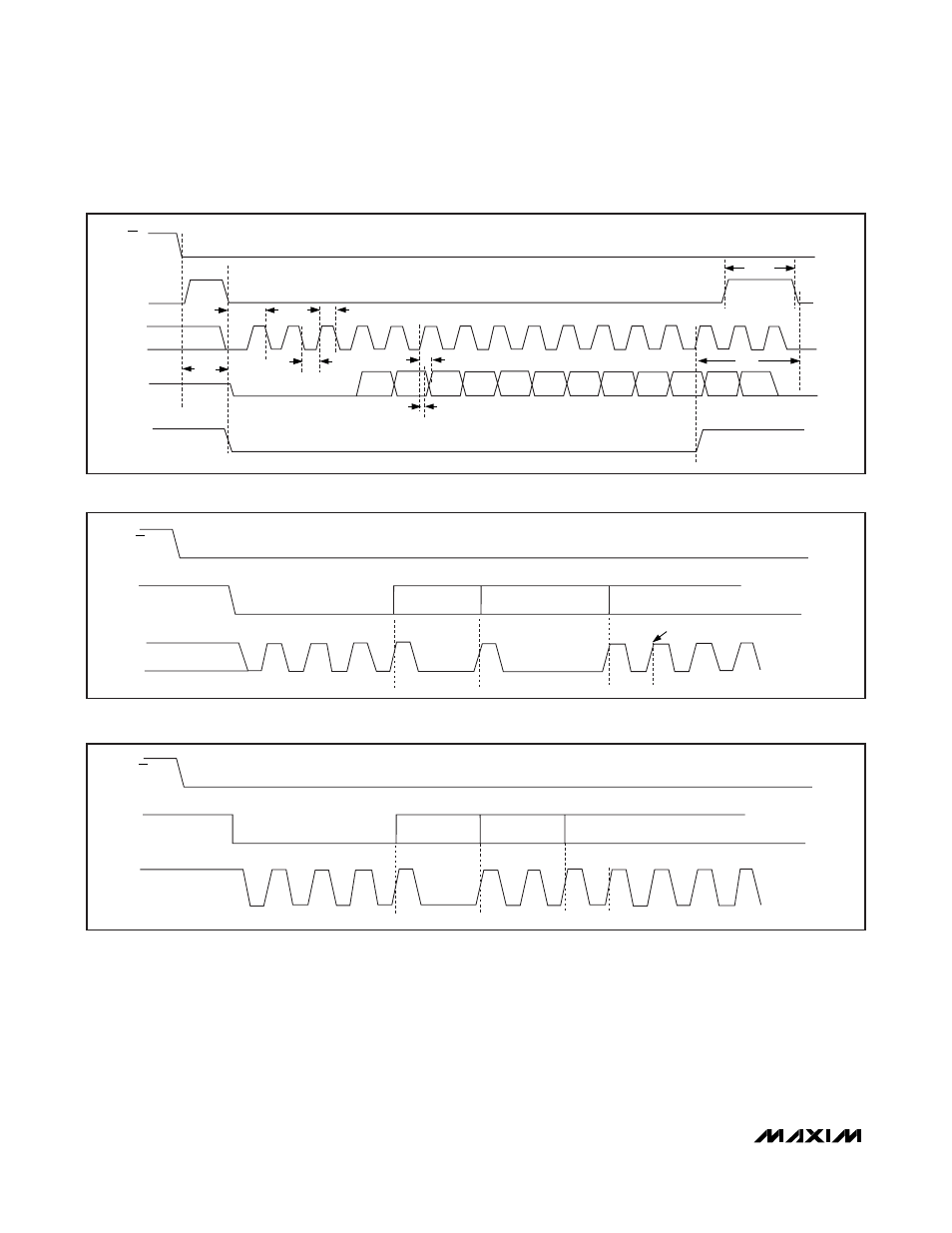
For continuous operation in single-output mode, pull
CNVST high after the 14th rising and before the 28th
rising edge of SCLK. In dual-output mode, if CNVST
returns high after the 14th rising and before the 16th
falling edge of SCLK, DOUT_ remains active so continu-
ous conversions can be sustained. If CNVST is low
during the 16th edge of SCLK (dual-conversion mode)
and the 28th falling edge of SCLK (single-output mode),
DOUT_ returns to its high-impedance state on the next
rising edge of CNVST or SCLK, enabling the serial inter-
face to be shared by multiple devices. See Figures 9
and 10 for single and continuous conversion timing
diagrams.
CNVST
SCLK
DOUT_
t
SETUP
t
CL
t
CH
t
DHOLD
t
DOUT
t
CSW
CS
t
ACQ
D11
D10
D9
D8
D7
D6
D5
D4
D3
14
13
1
t
CST
TRACKING
HOLD MODE
INTERNAL T/H STATE
D2
D1
D0
Figure 6. Detailed Serial-Interface Timing Diagram
CNVST
SCLK
1
2
3
4
14
28
POWER-DOWN CONTINUOUS
MODE
DOUT1 GOES HI-Z
DOUT1 HI-Z
29
CS
Figure 7. Single-Output CNVST Transition Modes
CNVST
SCLK
1
2
3
4
14
POWER-DOWN CONTINUOUS
MODE DOUT_ HI-Z
DOUT_ HI-Z
15
16
17
CS
Figure 8. Dual-Output CNVST Transition Modes