Table 3. throughput vs. channels sampled (t, 200ns, f, 10mhz) – Rainbow Electronics MAX1326 User Manual
Page 17
MAX1316–MAX1318/MAX1320–MAX1322/MAX1324–MAX1326
8-/4-/2-Channel, 14-Bit, Simultaneous-Sampling ADCs
with ±10V, ±5V, and 0 to +5V Analog Input Ranges
______________________________________________________________________________________
17
Data Throughput
The data throughput (f
TH
) of the MAX1316–MAX1318/
MAX1320–MAX1322/MAX1324–MAX1326 is a function
of the clock speed (f
CLK
). In internal-clock mode, f
CLK
=
10MHz. In external-clock mode, 100kHz
≤ f
CLK
≤
12.5MHz. When reading during conversion (Figures 5
and 6), calculate f
TH
as follows:
where N is the number of active channels and t
QUIET
includes acquistion time t
ACQ
. t
QUIET
is the period of bus
inactivity before the rising edge of CONVST. Typically use
t
QUIET
= t
ACQ
+ 50ns, and prevent disturbance on the
output bus from corrupting signal acquistion. See the
Starting a Conversion section for more information.
Reading a Conversion Result
Reading During a Conversion
Figures 5 and 6 show the interface signals for initiating a
read operation during a conversion cycle. These figures
show two channels selected for conversion. If more chan-
nels are selected, the results are available successively
every third clock cycle. CS can be low at all times; it can
be low during the RD cycles, or it can be the same as RD.
After initiating a conversion by bringing CONVST high,
wait for EOC to go low (about 1.6µs in internal-clock
mode or 17 clock cycles in external-clock mode) before
reading the first conversion result. Read the conversion
result by bringing RD low, thus latching the data to the
parallel digital-output bus. Bring RD high to release the
digital bus. Wait for the next falling edge of EOC (about
300ns in internal-clock mode or three clock cycles in
external-clock mode) before reading the next result.
When the last result is available, EOLC goes low.
f
t
x N
f
TH
QUIET
CLK
=
+
+
−
+
1
16
3
1
1
(
)
Table 3. Throughput vs. Channels Sampled (t
QUIET
= t
ACQ
= 200ns, f
CLK
= 10MHz)
CHANNELS
SAMPLED
(N)
CLOCK CYCLES
UNTIL LAST
RESULT
CLOCK CYCLE FOR
READING LAST
CONVERSION
TOTAL
CONVERSION
TIME (ns)
SAMPLES PER
SECOND
(ksps)
THROUGHPUT
PER CHANNEL
(ksps)
1
16
1
1900
526
526
2
19
1
2200
909
455
3
22
1
2500
1200
400
4
25
1
2800
1429
357
5
28
1
3100
1613
323
6
31
1
3400
1765
294
7
34
1
3700
1892
270
8
37
1
4000
2000
250
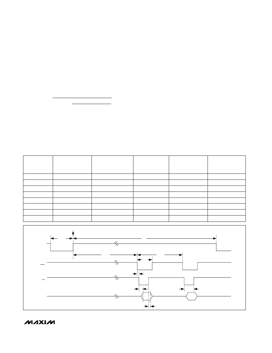
Figure 5. Read During Conversion—Two Channels Selected, Internal Clock
CONVST
CH0
TRACK
HOLD
D0–D13
SAMPLE
t
1
t
13
t
12
t
10
t
3
t
11
TRACK
CH1
t
CONV
t
NEXT
EOC
RD
t
20