Pin description (continued) – Rainbow Electronics MAX1326 User Manual
Page 11
MAX1316–MAX1318/MAX1320–MAX1322/MAX1324–MAX1326
8-/4-/2-Channel, 14-Bit, Simultaneous-Sampling ADCs
with ±10V, ±5V, and 0 to +5V Analog Input Ranges
______________________________________________________________________________________
11
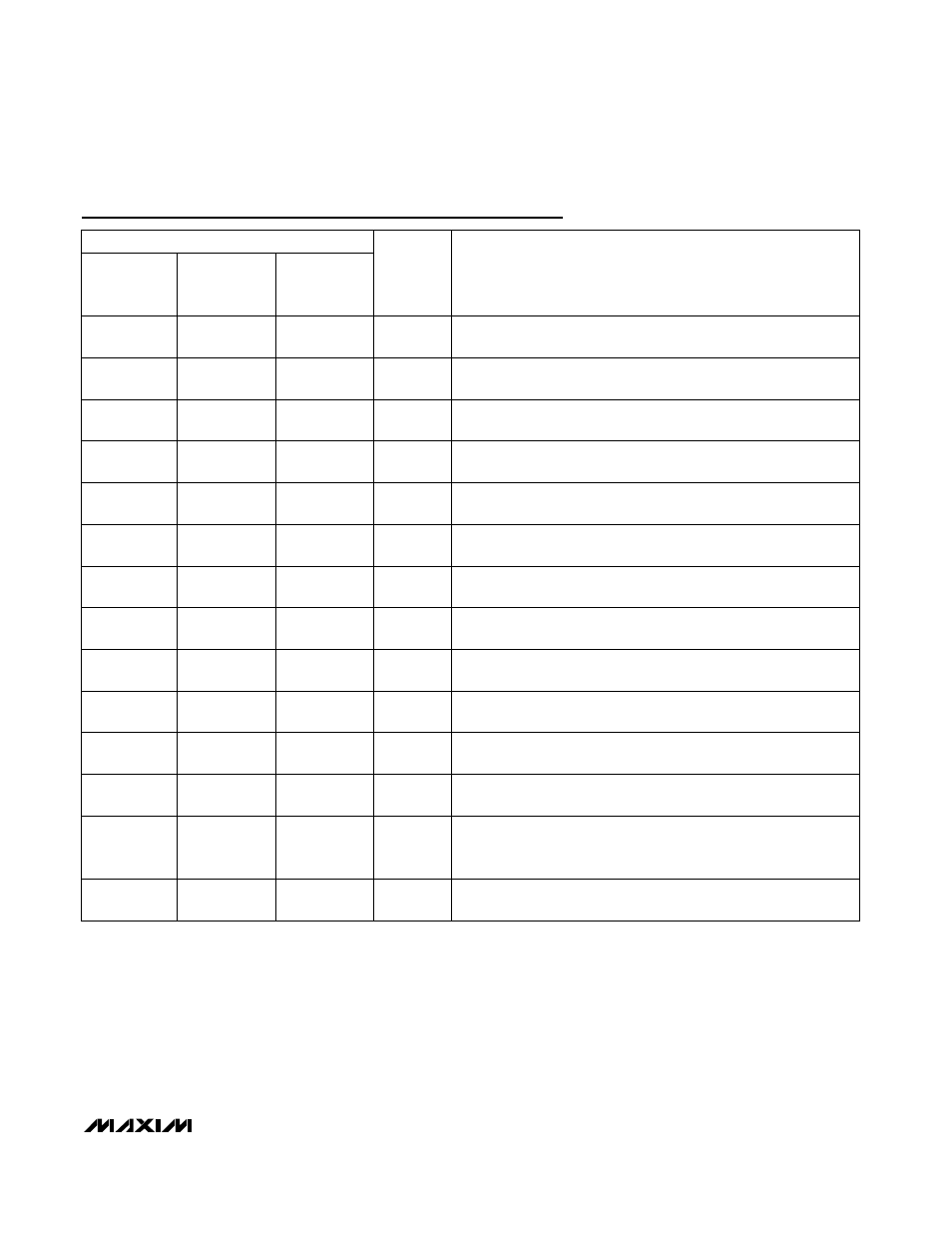
Pin Description (continued)
PIN
MAX1316
MAX1320
MAX1324
MAX1317
MAX1321
MAX1325
MAX1318
MAX1322
MAX1326
NAME
FUNCTION
27
27
27
D3
Digital I/O Bit 3 of 14-Bit Parallel Data Bus. High impedance when
RD = 1 or CS = 1.
28
28
28
D4
Digital I/O Bit 4 of 14-Bit Parallel Data Bus. High impedance when
RD = 1 or CS = 1.
29
29
29
D5
Digital I/O Bit 5 of 14-Bit Parallel Data Bus. High impedance when
RD = 1 or CS = 1.
30
30
30
D6
Digital I/O Bit 6 of 14-Bit Parallel Data Bus. High impedance when
RD = 1 or CS = 1.
31
31
31
D7
Digital I/O Bit 7 of 14-Bit Parallel Data Bus. High impedance when
RD = 1 or CS = 1.
32
32
32
D8
Digital Out Bit 8 of 14-Bit Parallel Data Bus. High impedance when
RD = 1 or CS = 1.
33
33
33
D9
Digital Out Bit 9 of 14-Bit Parallel Data Bus. High impedance when
RD = 1 or CS = 1.
34
34
34
D10
Digital Out Bit 10 of 14-Bit Parallel Data Bus. High impedance when
RD = 1 or CS = 1.
35
35
35
D11
Digital Out Bit 11 of 14-Bit Parallel Data Bus. High impedance when
RD = 1 or CS = 1.
36
36
36
D12
Digital Out Bit 12 of 14-Bit Parallel Data Bus. High impedance when
RD = 1 or CS = 1.
37
37
37
D13
Digital Out Bit 13 of 14-Bit Parallel Data Bus. High impedance when
RD = 1 or CS = 1.
38
38
38
DV
DD
Digital-Supply Input. Apply +2.7V to +5.25V to DV
DD
. Bypass DV
DD
to DGND with a 0.1µF capacitor.
39
39
39
DGND
Digital-Supply GND. DGND is the power return for DV
DD
. Connect
DGND to AGND at only one point (see the Layout, Grounding, and
Bypassing section).
40
40
40
EOC
End-of-Conversion Output. EOC goes low to indicate the end of a
conversion. EOC returns high after one clock period.