Pin description (continued) – Rainbow Electronics MAX1326 User Manual
Page 12
MAX1316–MAX1318/MAX1320–MAX1322/MAX1324–MAX1326
8-/4-/2-Channel, 14-Bit, Simultaneous-Sampling ADCs
with ±10V, ±5V, and 0 to +5V Analog Input Ranges
12
______________________________________________________________________________________
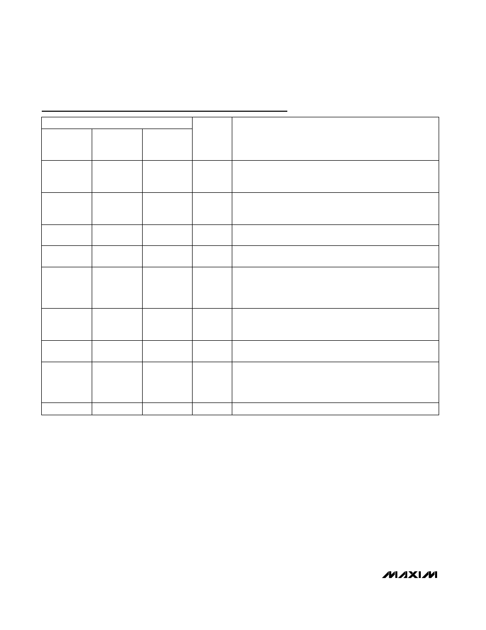
Pin Description (continued)
PIN
MAX1316
MAX1320
MAX1324
MAX1317
MAX1321
MAX1325
MAX1318
MAX1322
MAX1326
NAME
FUNCTION
41
41
41
EOLC
End-of-Last-Conversion Output. EOLC goes low to indicate the end
of the last conversion. EOLC returns high when CONVST goes low
for the next conversion sequence.
42
42
42
RD
Read Input. When RD and CS go low, the device initiates a read
command of the parallel data buses, D0–D13. D0–D13 are high
impedance while either RD or CS is high.
43
43
43
WR
Write Input. The write command initiates when WR and CS go low. A
write command loads the configuration byte on D0–D7.
44
44
44
CS
Chip-Select Input. Pulling CS low activates the digital interface.
D0–D13 are high impedance while either CS or RD is high.
45
45
45
CONVST
Convert-Start Input. Driving CONVST high places the device in hold
mode and initiates the conversion process. The analog inputs are
sampled on the rising edge of CONVST. When CONVST is low, the
analog inputs are tracked.
46
46
46
CLK
External-Clock Input. CLK accepts an external-clock signal up to
15MHz. Connect CLK to DGND for internally clocked conversions.
To select external-clock mode, set INTCLK/EXTCLK = 0.
47
47
47
SHDN
Shutdown Input. Set SHDN = 0 for normal operation. Set SHDN = 1
for shutdown mode.
48
48
48
ALLON
Enable-All-Channels Input. Drive ALLON high to enable all input
channels. When ALLON is low, only input channels selected as
active are powered. Select channels as active using the
configuration register.
—
9–12
7–12
I.C.
Internally Connected. Connect I.C. to AGND. For factory use only.