Chip information – Rainbow Electronics MAX1855 User Manual
Page 30
MAX1716/MAX1854/MAX1855
High-Speed, Adjustable, Synchronous Step-Down
Controllers with Integrated Voltage Positioning
30
______________________________________________________________________________________
3) Group the gate-drive components (BST diode and
capacitor, V
DD
bypass capacitor) together near the
controller IC.
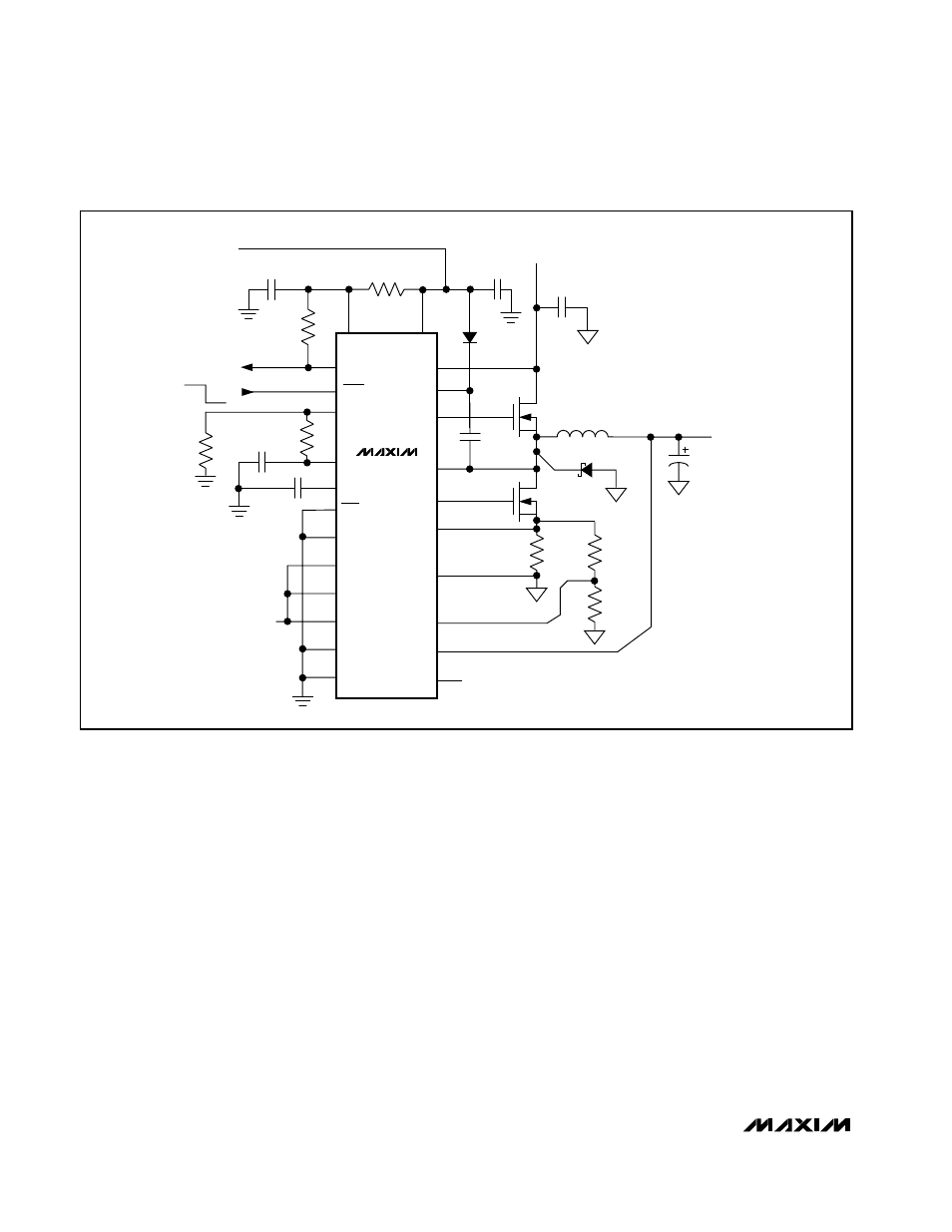
4) Make the DC-DC controller ground connections as
shown in Figure 1. This diagram can be viewed as
having three separate ground planes: output ground,
where all the high-power components go; the GND
plane, where the GND pin and V
DD
bypass capaci-
tors go; and an analog ground plane where sensitive
analog components go. The analog ground plane
and GND plane must meet only at a single point
directly beneath the IC. These two planes are then
connected to the high-power output ground with a
short connection from GND to the source of the low-
side MOSFET (the middle of the star ground). This
point must also be very close to the output capacitor
ground terminal.
5) Connect the output power planes (V
CORE
and sys-
tem ground planes) directly to the output filter
capacitor positive and negative terminals with multi-
ple vias. Place the entire DC-DC converter circuit as
close to the CPU as is practical.
___________________Chip Information
TRANSISTOR COUNT: 3729
V
CC
C
OUT
(4) 220
µF
D2
L1
1.0
µH
1.3V OUTPUT
UP TO 12A
SHDN
VGATE
D1
C4
1
µF
C3
0.1
µF
Q1
Q2
C5
1
µF
R3
10
Ω
C
IN
(4) 10
µF
BATTERY (V
BATT
)
7V TO 24V
REF
ILIM
CC
+5V INPUT
BIAS SUPPLY
POWER-GOOD
INDICATOR
DL
LX
V+
DH
BST
CS
PGND
VPS
FB
TON
V
DD
MAX1716
MAX1854
MAX1855
SKIP
D0
D1
D2
D3
D4
GND
R6
100k
Ω
TO V
CC
R4
100k
Ω
R5
300k
Ω
C2
47pF
C1
0.22
µF
ON OFF
R2
2k
Ω
FLOAT (300kHz)
R1
1k
Ω
R
SENSE
3.5m
Ω
Q1: IRF7811
INTERNATIONAL RECTIFIER
Q2: (2) IRF7811
INTERNATIONAL RECTIFIER
D1: CMPSH-3
CENTRAL SEMICONDUCTOR
D2: CMSH2-60
CENTRAL SEMICONDUCTOR
MAX1716 DAC CODE SHOWN
Figure 11. Low-Current Application (Circuit #2)