Rainbow Electronics MAX1855 User Manual
Page 15
MAX1716/MAX1854/MAX1855
High-Speed, Adjustable, Synchronous Step-Down
Controllers with Integrated Voltage Positioning
______________________________________________________________________________________
15
tor is low, the low-side switch current is below the cur-
rent-limit threshold, and the minimum off-time one-shot
has timed out.
On-Time One-Shot (TON)
The heart of the PWM core is the one-shot that sets the
high-side switch on-time. This fast, low-jitter, adjustable
one-shot includes circuitry that varies the on-time in
response to the input and output voltages. The high-
side switch on-time is inversely proportional to V+, and
directly proportional to the output voltage as set by the
DAC code. This algorithm results in a nearly constant
switching frequency despite the lack of a fixed-frequen-
cy clock generator. The benefits of a constant switch-
ing frequency are twofold: first, the frequency can be
selected to avoid noise-sensitive regions, such as the
455kHz IF band; second, the inductor ripple-current
operating point remains relatively constant, resulting in
easy design methodology and predictable output volt-
age ripple.
On-Time = K
× (V
OUT
+ 75mV) / V+
where K is set by the TON pin-strap connection, and
75mV is an approximation to accommodate for the
expected drop across the low-side MOSFET switch and
current-sense resistor (Table 3).
The on-time one-shot has good accuracy at the operat-
ing points specified in the Electrical Characteristics
table. On-times at operating points far removed from
the conditions specified in the Electrical Characteristics
table can vary over a wide range. For example, the
550kHz setting will typically run about 10% slower with
inputs much greater than the +5V due to the very short
on-times required.
While the on-time is set by TON, V+, and the output
voltage, other factors also contribute to the overall
V
CC
C
OUT
(5) 220
µF
PANASONIC
D2
L1
0.68
µH
1.6V OUTPUT
UP TO 18A
SHDN
VGATE
D1
C4
1
µF
C3
0.1
µF
Q1
Q2
C5
1
µF
R3
10
Ω
C
IN
(5) 10
µF
BATTERY (V
BATT
)
7V TO 24V
REF
ILIM
CC
+5V INPUT
BIAS SUPPLY
POWER-GOOD
INDICATOR
DL
LX
V+
DH
BST
CS
PGND
VPS
FB
TON
V
DD
MAX1716
MAX1854
MAX1855
SKIP
D0
D1
D2
D3
D4
GND
R6
100k
Ω
TO V
CC
R4
100k
Ω
R5
200k
Ω
C2
47pF
C1
0.22
µF
ON OFF
R2
1k
Ω
FLOAT (300kHz)
MAX1716 DAC CODE SHOWN
R1
1k
Ω
R
SENSE
3m
Ω
Q1: (2) IRF7811
INTERNATIONAL RECTIFIER
Q2: (2) IRF7811
INTERNATIONAL RECTIFIER
D1: CMPSH-3
CENTRAL SEMICONDUCTOR
D2: CMSH2-60
CENTRAL SEMICONDUCTOR
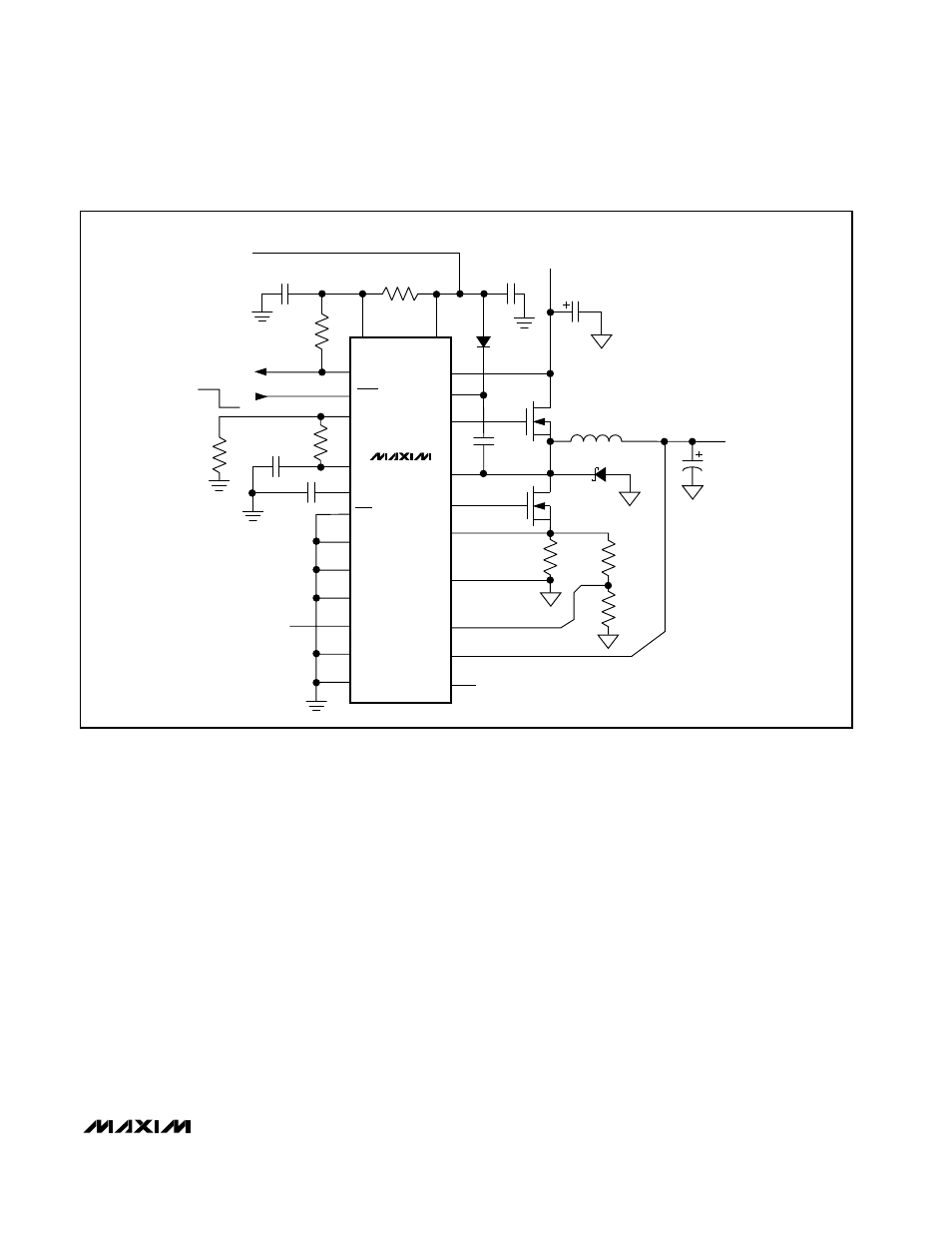
Figure 1. Standard High-Power Application (Circuit #1)