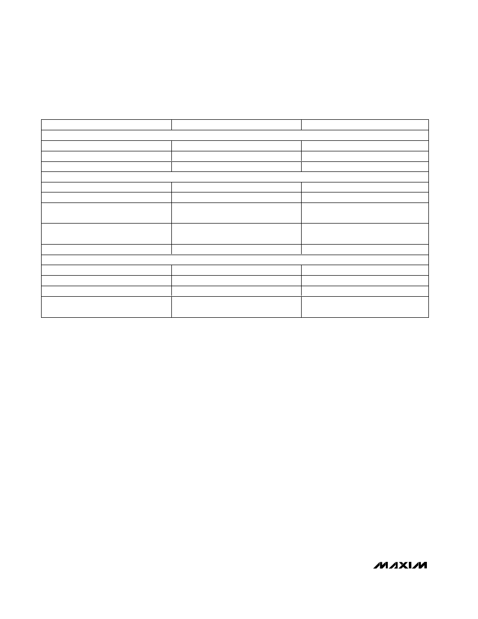
Detailed description, Table 2. component suppliers – Rainbow Electronics MAX1855 User Manual
Page 14
MAX1716/MAX1854/MAX1855
High-Speed, Adjustable, Synchronous Step-Down
Controllers with Integrated Voltage Positioning
14
______________________________________________________________________________________
_______________Detailed Description
The MAX1716/MAX1854/MAX1855 buck controllers are
targeted for low-voltage, high-current CPU core power
supplies for notebook computers that typically require
18A (or greater) load steps. The proprietary Quick-
PWM pulse-width modulator in the converter is specifi-
cally designed for handling fast load steps while
maintaining a relatively constant operating frequency
and inductor operating point over a wide range of input
voltages. The Quick-PWM architecture circumvents the
poor load-transient timing problems of fixed-frequency
current-mode PWMs while also avoiding the problems
caused by widely varying switching frequencies in con-
ventional constant on-time and constant off-time PFM
schemes.
+5V Bias Supply (V
CC
and V
DD
)
The MAX1716/MAX1854/MAX1855 require an external
+5V bias supply in addition to the battery. Typically this
+5V bias supply is the notebook’s 95% efficient +5V
system supply. Keeping the bias supply external to the
IC improves efficiency and eliminates the cost associat-
ed with the +5V linear regulator that would otherwise be
needed to supply the PWM circuit and gate drivers. If
stand-alone capability is needed, the +5V supply can
be generated with an external linear regulator.
The +5V bias supply powers V
CC
(PWM controller) and
V
DD
(gate-drive power). The maximum current is:
I
BIAS
= I
CC
+
ƒ × (Q
G1
+ Q
G2
) = 10mA to 40mA (typ)
where I
CC
is 700µA (typ),
ƒ is the switching frequency,
and Q
G1
and Q
G2
are the MOSFET data sheet total
gate-charge specification limits at V
GS
= 5V.
The battery input (V+) and +5V bias inputs (V
CC
and
V
DD
) can be connected together if the input source is a
fixed 4.5V to 5.5V supply. If the +5V bias supply is
powered up prior to the battery supply, the enable sig-
nal (SHDN) must be delayed until the battery voltage is
present to ensure startup.
Free-Running, Constant-On-Time PWM
Controller with Input Feed-Forward
The Quick-PWM control architecture is a constant-on-
time, current-mode type with voltage feed-forward
(Figure 2). This architecture relies on the output ripple
voltage to provide the PWM ramp signal. Thus, the out-
put filter capacitor’s ESR acts as a feedback resistor.
The control algorithm is simple: the high-side switch on-
time is determined solely by a one-shot whose period is
inversely proportional to input voltage and directly pro-
portional to output voltage (see On-Time One-Shot).
Another one-shot sets a minimum off-time (400ns typ).
The on-time one-shot is triggered if the error compara-
MANUFACTURER
PHONE (COUNTRY CODE)
WEBSITE
MOSFETs
Fairchild Semiconductor
(1) 888-522-5372
www.fairchildsemi.com
International Rectifier
(1) 310-322-3331
www.irf.com
Siliconix
(1) 203-268-6261
www.vishay.com
CAPACITORS
Kemet
(1) 408-986-0424
www.kemet.com
Panasonic
(1) 847-468-5624
www.panasonic.com
Sanyo
(65) 281-3226 (Singapore)
(1) 408-749-9714
www.secc.co.jp
Taiyo Yuden
(03) 3667-3408 (Japan)
(1) 408-573-4150
www.t-yuden.com
TDK
(1) 847-390-4373
www.tdk.com
INDUCTORS
Coilcraft
(1) 800-322-2645
www.coilcraft.com
Coiltronics
(1) 561-752-5000
www.coiltronics.com
Sumida
(1) 408-982-9660
www.sumida.com
Sumitomo
(1) 408-451-8441 (USA)
81 75 961-3141 (Japan)
www.ssmc.co.jp
Table 2. Component Suppliers