Rainbow Electronics MAX1855 User Manual
Page 25
MAX1716/MAX1854/MAX1855
High-Speed, Adjustable, Synchronous Step-Down
Controllers with Integrated Voltage Positioning
______________________________________________________________________________________
25
the complete expression for the voltage-positioned out-
put depends only upon the value of the current-sense
resistor and the load current:
V
OUT
≈ V
OUT(PROG)
(1 - A
VPS
I
LOAD
R
SENSE
)
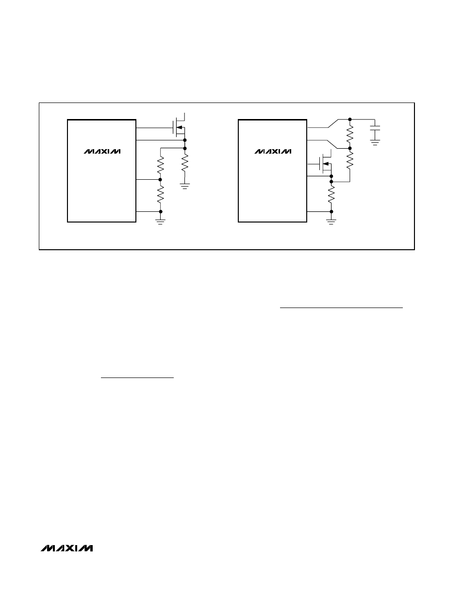
Some applications require the addition of a positive off-
set to the output voltage to ensure that it remains within
the load specifications. The positive offset may be gen-
erated by connecting a resistive divider from REF to
VPS to CS (Figure 6a). Set R1 to 1k
Ω, and use the fol-
lowing equation to calculate R3:
where V
REF
is typically 2.0V, and V
OFFSET
is the
required positive offset voltage. When attenuating the
voltage-positioning signal, replace R1 with the parallel
combination of R1 and R2 (R1//R2), where R2 is the
attenuation resistor (Figure 6b).
After a load transient, the output instantly changes by
ESR
COUT
× ∆I
LOAD
. Setting the load-dependent volt-
age position to match this initial load step allows the
output voltage to change by ESR
COUT
× ∆I
LOAD
and
stay there as long as the load remains unchanged (see
Voltage Positioning and Effective Efficiency). To set the
voltage position equal to the initial voltage drop gener-
ated by the output capacitor’s ESR, select R
SENSE
=
ESR
COUT
/ (V
OUT(PROG)
× A
VPS
).
For applications using a larger current-sense resistor,
adjust V
VPS
by connecting a resistive divider from CS
to VPS to PGND (Figure 6b). Set R1 to 1k
Ω, and use the
following equation to calculate R2:
The MAX1716/MAX1854/MAX1855 voltage-positioning
circuit has several advantages over older circuits,
which added a fixed voltage offset on the sense point
and used a low-value resistor in series with the output.
The new circuit can use the same current-sense resis-
tor for both voltage positioning and current-limit detec-
tion. This simultaneously provides accurate current
limiting and voltage positioning. Since the new circuit
adjusts the output voltage within the control loop, the
voltage-positioning signal may be internally amplified.
The additional gain allows the use of low-value current-
sense resistors, so the power dissipated in this sense
resistor is significantly lower than a single resistor con-
nected directly in series with the output.
Voltage-Positioning Compensation (CC)
The voltage-positioning compensation capacitor filters
the amplified VPS signal, allowing the user to adjust the
dynamics of the voltage-positioning loop. The imped-
ance at this node is approximately 200k
Ω, so the pole
provided by this node can be approximated by 1 / (2
×
π × RC). The response time is set with a 47pF to
1000pF capacitor from CC to GND.
R
R
ESR
A
V
R
ESR
COUT
VPS OUT PROG
SENSE
COUT
2
1
=
−
(
)
R
R
V
A
V
V
REF VPS OUT PROG
OFFSET
3
1
1
=
−
(
)
MAX1716
MAX1854
MAX1855
DL
CS
VPS
PGND
N
R1
R
SENSE
a) SCALED VOLTAGE POSITION SIGNAL
b) POSITIVE NO-LOAD VOLTAGE POSITIONING
R2
MAX1716
MAX1854
MAX1855
REF
VPS
CS
DL
PGND
R3
Q2
R1
R
SENSE
C
REF
0.22
µF
Figure 6. Voltage-Positioning Configurations