Electrical characteristics (continued) – Rainbow Electronics MAX1499 User Manual
Page 5
MAX1497/MAX1499
3.5- and 4.5-Digit, Single-Chip ADCs with LED
Drivers and µC Interface
_______________________________________________________________________________________
5
PARAMETER
SYMBOL
CONDITIONS
MIN
TYP
MAX
UNITS
DV
DD
= 5V
320
DV
DD
= 3.3V
180
DV
DD
Current (Notes 8, 9)
I
DVDD
Standby mode
20
µA
LED Drivers Bias Current
From AV
DD
or V
DD
120
µA
LED DRIVERS
(Table 6)
LED Supply Voltage
V
LED
2.70
5.25
V
LED Shutdown Supply Current
I
SHDN
LED driver shutdown mode
10
µA
LED Supply Current
I
LED
Seven segments and decimal point on,
R
ISET
= 25kΩ
176
mA
MAX1499
512
Display Scan Rate
f
OSC
MAX1497
640
Hz
Segment Current Slew Rate
∆I
SEG
/∆t
25
mA/µs
DIG_ Voltage Low
V
DIG
I
DIG_
= 176mA
0.178
0.300
V
Segment Drive Source Current
Matching
∆I
SEG
±3
±10
%
Segment Drive Source Current
I
SEG
V
LED
- V
SEG
= 0.6V, R
ISET
= 25kΩ
16
20
25.5
mA
Interdigit Blanking Time
4
µs
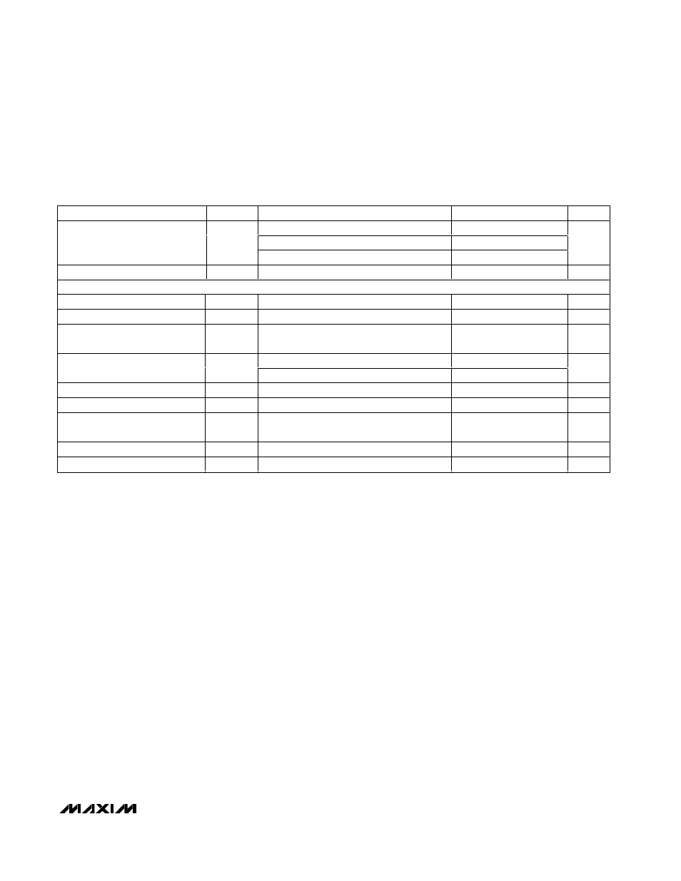
ELECTRICAL CHARACTERISTICS (continued)
(AV
DD
= DV
DD
= V
DD
= +2.7V to +5.25V, GND = 0, GLED = 0, V
LED
= +2.7V to +5.25V, V
REF+
- V
REF-
= 2.048V (external reference)
C
REF+
= C
REF-
= 0.1µF, C
VNEG
= 0.1µF. Internal clock mode, unless otherwise noted. All specifications are at T
A
= T
MIN
to T
MAX
.
Typical values are at T
A
= +25°C, unless otherwise noted.)