Thermocouple measurement, Transfer functions – Rainbow Electronics MAX1499 User Manual
Page 26
MAX1497/MAX1499
3.5- and 4.5-Digit, Single-Chip ADCs with LED
Drivers and µC Interface
26
______________________________________________________________________________________
Thermocouple Measurement
Figure 16 shows a connection from a thermocouple to
the MAX1497/MAX1499. In this application, the
MAX1497/MAX1499 take advantage of the on-chip
input buffers that allow large source impedances on the
front end. The decoupling capacitors reduce noise
pickup from the thermocouple leads. To place the dif-
ferential voltage from the thermocouple at a suitable
common-mode voltage, the AIN- input of the MAX1497/
MAX1499 is biased to GND. Use an external tempera-
ture sensor, such as the DS75, and a µC to perform
cold-junction temperature compensation.
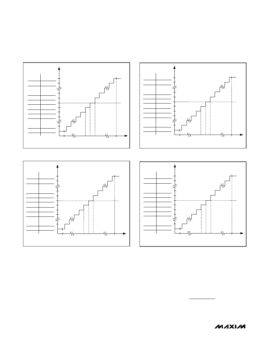
Transfer Functions
Figures 17–20 show the transfer functions of the
MAX1497/MAX1499. The output data is stored in the
ADC data register in two’s complement.
The transfer function for the MAX1499 with AIN+ - AIN-
≥ 0, RANGE = 0 is:
COUNTS
V
V
V
V
AIN
AIN
REF
REF
.
,
=
×
+
+
−
−
−
−
1 024
20 000
7CFh
7CFh
002h
001h
000h
FFFh
FFEh
FFDh
830h
<830h
-200mV
0
ANALOG INPUT VOLTAGE
+200mV
ADC RESULT
LED
1 - - -
1999
2
1
0
- 0
- 1
- 2
-1999
- 1 - - -
-100µV 100µV
Figure 19. MAX1497 Transfer Function, ±200mV Range
>7CFh
7CFh
002h
001h
000h
FFFh
FFEh
FFDh
830h
<830h
-2V
0
ANALOG INPUT VOLTAGE
+2V
ADC RESULT
LED
1 - - -
1999
2
1
0
- 0
- 1
- 2
-1999
- 1 - - -
-1mV
1mV
Figure 20. MAX1497 Transfer Function, ±2V Range
>4E1Fh
4E1Fh
0002h
0001h
0000h
FFFFh
FFFEh
FFFDh
B1E0h
-2V 0 ANALOG INPUT VOLTAGE +2V ADC RESULT LED 1 - - - - 19,999 2 1 0 - 0 - 1 - 2 -19,999 - 1 - - - - -100µV 100µV Figure 17. MAX1499 Transfer Function, ±2V Range 4E1Fh 4E1Fh 0002h 00001h 0000h FFFFh FFFEh FFFDh B1E0h -200mV 0 ANALOG INPUT VOLTAGE +200mV ADC RESULT LED 1 - - - - 19,999 2 1 0 - 0 - 1 - 2 -19,999 - 1 - - - - -10µV 10µV Figure 18. MAX1499 Transfer Function, ±200mV Range