Rainbow Electronics MAX1499 User Manual
Page 21
MAX1497/MAX1499
3.5- and 4.5-Digit, Single-Chip ADCs with LED
Drivers and µC Interface
______________________________________________________________________________________
21
Default values:
8300h (for 3.5-digit, -2000)
B1E0h (for 4.5-digit, -20,000)
The underrange data register is 16-bit read/write regis-
ter (D15 is the MSB). When the conversion result falls
below the value in the underrange register, the UNDR
bit in the status register sets to 1. The LED shows a -1
followed by four dashes for the MAX1499 or a -1 fol-
lowed by three dashes for the MAX1497 (Table 4).
The data is represented in two’s complement format.
Default values: 0000h
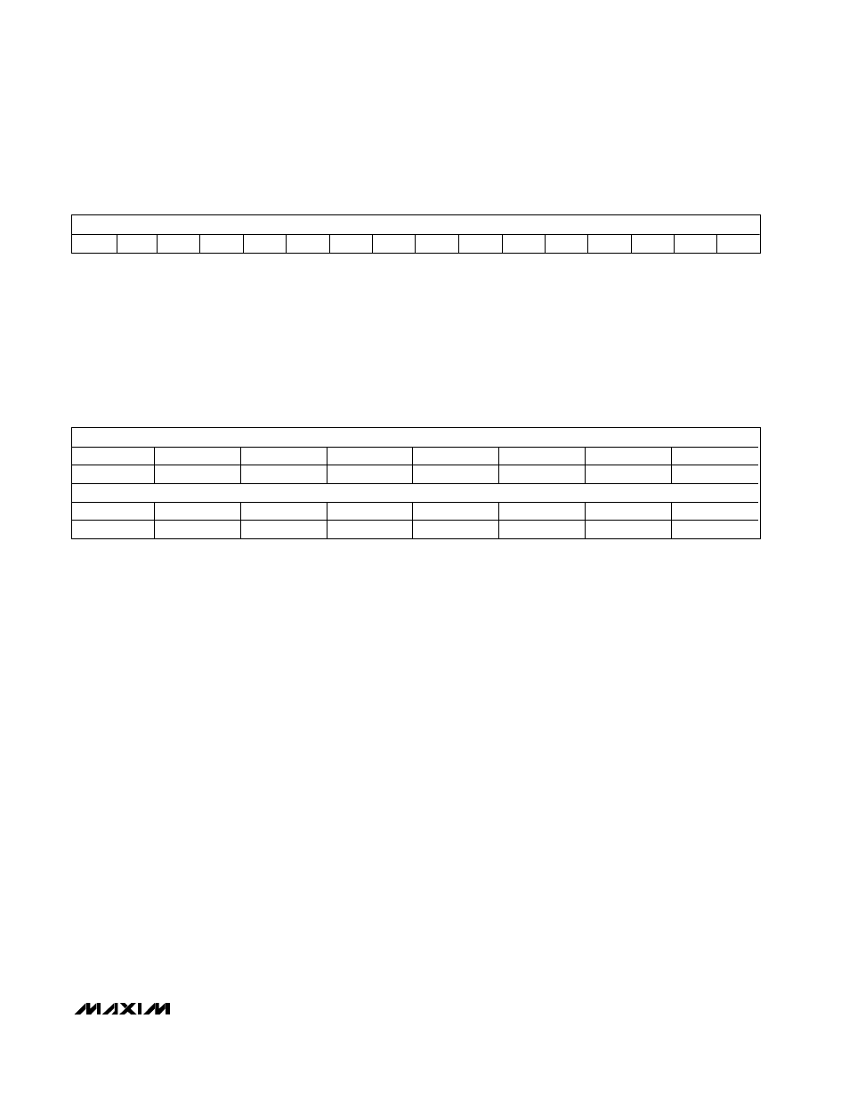
Underrange Register (Read/Write)
MSB
LSB
D15
D14
D13
D12
D11
D10
D9
D8
D7
D6
D5
D4
D3
D2
D1
D0
LED Segment-Display Register 1 (Read/Write)
MSB
Bit 15
Bit 14
Bit 13
Bit 1
Bit 11
Bit 10
Bit 9
Bit 8
A1
G1
D1
F1
E1
DP2
X
B0
LSB
Bit 7
Bit 6
Bit 5
Bit 4
Bit 3
Bit 2
Bit 1
Bit 0
C0
A0
G0
D0
F0
E0
DP1
0
LED segment-display register 1 is a 16-bit read/write
register. When the LED bit (in the control register) is set
to 1, the MAX1497/MAX1499 provide direct access to
individual LED segments. The bits in the LED segment-
display register determine if a segment is on or off.
Write a zero to turn on a segment and a 1 to turn off a
segment.
DP1: Segment DP driver bit of digit 1. The default value
turns on the LED segment.
E0: Segment E driver bit of digit 0. The default value
turns on the LED segment.
F0: Segment F driver bit of digit 0. The default value
turns on the LED segment.
D0: Segment D driver bit of digit 0. The default value
turns on the LED segment.
G0: Segment G driver bit of digit 0. The default value
turns on the LED segment.
A0: Segment A driver bit of digit 0. The default value
turns on the LED segment.
C0: Segment C driver bit of digit 0. The default value
turns on the LED segment.
B0: Segment B driver bit of digit 0. The default value
turns on the LED segment.
X: Don’t care.
DP2: Segment DP driver bit of digit 2. The default value
turns on the LED segment.
E1: Segment E driver bit of digit 1. The default value
turns on the LED segment.
F1: Segment F driver bit of digit 1. The default value
turns on the LED segment.
D1: Segment D driver bit of digit 1. The default value
turns on the LED segment.
G1: Segment G driver bit of digit 1. The default value
turns on the LED segment.
A1: Segment A driver bit of digit 1. The default value
turns on the LED segment.