Applications information, Table 7. detailed sspcon register contents – Rainbow Electronics MAX1168 User Manual
Page 24
MAX1167/MAX1168
Multichannel, 16-Bit, 200ksps Analog-to-Digital
Converters
24
______________________________________________________________________________________
Applications Information
Internal Reference
The internal bandgap reference provides a buffered
+4.096V. Bypass REFCAP with a 0.1µF capacitor to
AGND and REF with a 1µF capacitor to AGND. For best
results, use low-ESR, X5R/X7R ceramic capacitors.
Allow 5ms for the reference and buffer to wake up from
full power-down (see Table 5).
External Reference
The MAX1167/MAX1168 accept an external reference
with a voltage range between +3.8V and AV
DD
. Connect
the external reference directly to REF. Bypass REF to
AGND with a 10µF capacitor. When not using a low-ESR
bypass capacitor, use a 0.1µF ceramic capacitor in paral-
lel with the 10µF capacitor. Noise on the reference
degrades conversion accuracy.
The input impedance at REF is 37k
Ω for DC currents.
During a conversion, the external reference at REF
must deliver 118µA of DC load current and have an out-
put impedance of 10
Ω or less.
For optimal performance, buffer the reference through
an op amp and bypass the REF input. Consider the
equivalent input noise (40µV
RMS
) of the MAX1167/
MAX1168 when choosing a reference.
Internal/External Oscillator
Select either an external (0.1MHz to 4.8MHz) or the
internal 4MHz (typ) clock to perform conversions
(Table 6). The external clock shifts data in and out of
the MAX1167/MAX1168 in either clock mode.
When using the internal clock mode, the internal oscilla-
tor controls the acquisition and conversion processes,
while the external oscillator shifts data in and out of the
MAX1167/MAX1168. Turn off the external clock (SCLK)
when the internal clock is on to realize lowest noise per-
formance. The internal clock remains off in external
clock mode.
Input Buffer
Most applications require an input-buffer amplifier to
achieve 16-bit accuracy. The input amplifier must have
a slew rate of at least 2V/µs and a unity-gain bandwidth
of at least 10MHz to complete the required output-volt-
age change before the end of the acquisition time.
At the beginning of the acquisition, the internal sam-
pling capacitor array connects to AIN_ (the amplifier
input), causing some disturbance on the output of the
buffer. Ensure the sampled voltage has settled before
the end of the acquisition time.
CONTROL BIT
SETTINGS
SYNCHRONOUS SERIAL-PORT CONTROL REGISTER (SSPCON)
WCOL
BIT7
X
Write Collision Detection Bit
SSPOV
BIT6
X
Receive Overflow Detection Bit
SSPEN
BIT5
1
Synchronous Serial-Port Enable Bit:
0: Disables serial port and configures these pins as I/O port pins.
1: Enables serial port and configures SCK, SDO, and SCI pins as serial
port pins.
CKP
BIT4
0
Clock Polarity Select Bit. CKP = 0 for SPI master-mode selection.
SSPM3
BIT3
0
SSPM2
BIT2
0
SSPM1
BIT1
0
SSPM0
BIT0
1
Synchronous Serial-Port Mode Select Bit. Sets SPI master mode and
selects f
CLK
= f
OSC
/ 16.
Table 7. Detailed SSPCON Register Contents
X = Don’t care.
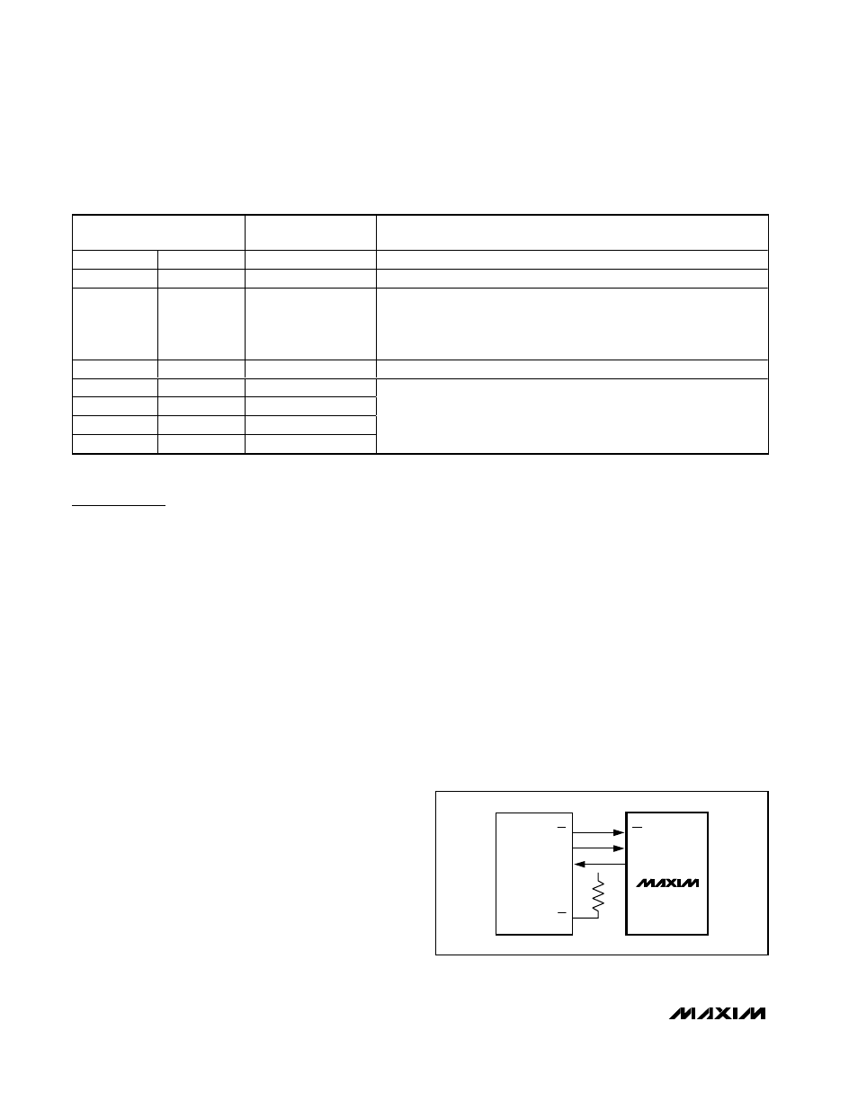
QSPI
SCLK
DOUT
CS
SCK
MISO
V
DD
SS
CS
MAX1167
MAX1168
Figure 21a. QSPI Connections