Rainbow Electronics MAX1168 User Manual
Page 13
The MAX1168 features a 16-bit-wide data-transfer
mode that includes a longer acquisition time (11.5
clock cycles). Longer acquisition times are useful in
applications with input source resistances greater than
1k
Ω. Noise increases when using large source resis-
tances. To improve the input signal bandwidth under
AC conditions, drive AIN_ with a wideband buffer
(>10MHz) that can drive the ADC’s input capacitance
and settle quickly.
Input Bandwidth
The ADC’s input-tracking circuitry has a 4MHz small-
signal bandwidth, making possible the digitization of
high-speed transient events and the measurement of
periodic signals with bandwidths exceeding the ADC’s
sampling rate by using undersampling techniques. To
avoid aliasing of unwanted, high-frequency signals into
the frequency band of interest, use anti-alias filtering.
Analog Input Protection
Internal protection diodes, which clamp the analog
input to AV
DD
or AGND, allow the input to swing from
(AGND - 0.3V) to (AV
DD
+ 0.3V) without damaging the
device. If the analog input exceeds 300mV beyond the
supplies, limit the input current to 10mA.
MAX1167/MAX1168
Multichannel, 16-Bit, 200ksps Analog-to-Digital
Converters
______________________________________________________________________________________
13
REFERENCE
REF
REFCAP
AV
DD
DV
DD
AGND
AGND
DGND
AIN0
AIN1
AIN2
AIN3
SCLK
CS
DIN
ANALOG-INPUT
MULTIPLEXER
MULTIPLEXER
CONTROL
ACCUMULATOR
MEMORY
INPUT REGISTER
BIAS
OSCILLATOR
OUTPUT
DOUT
EOC
ANALOG-SWITCH FINE TIMING
SUCCESSIVE-APPROXIMATION
REGISTER
MAX1168
DAC
BUFFER
AIN4
AIN5
AIN6
AIN7
AZ
RAIL
COMPARATOR
DSPX
DSEL
DSPR
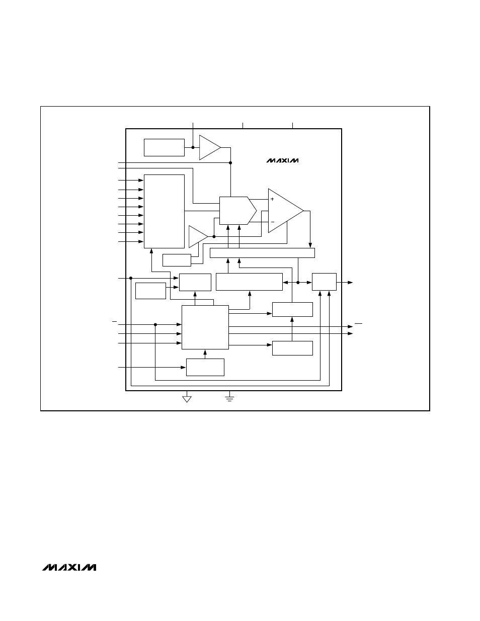
Figure 4. MAX1168 Functional Diagram