Detailed description – Rainbow Electronics MAX1364 User Manual
Page 9
Detailed Description
The MAX1363/MAX1364 4-channel ADCs use succes-
sive-approximation conversion techniques and fully dif-
ferential input track/hold (T/H) circuitry to capture and
convert analog signals to a serial 12-bit digital output.
The MAX1363/MAX1364 feature a monitor mode with
programmable trip thresholds and window comparator.
The monitor function asserts an interrupt when any
channel violates the programmed upper or lower
thresholds. SMBus alert response allows the host
microcontroller (µC) to quickly identify which device
caused the interrupt. A programmable delay between
monitoring intervals lowers power consumption at lower
monitor rates.
The MAX1363/MAX1364 integrate an internal voltage
reference and clock. The software configures the ana-
log inputs for unipolar/bipolar and single-ended/fully
differential operation. Integrated first-in/first-out (FIFO)
allows conversion of all channels, or eight conversions
on a selected channel to reduce interface overhead. An
I
2
C-compatible serial interface complies with standard,
fast, and high-speed (1.7MHz) modes.
MAX1363/MAX1364
4-Channel, 12-Bit System Monitors with Programmable
Trip Window and SMBus Alert Response
_______________________________________________________________________________________
9
t
SU.STA
t
SU.DAT
t
HIGH
t
R
t
F
t
HD.DAT
t
HD.STA
S
Sr
ACK
9
SCL
SDA
t
SU.STA
t
LOW
t
BUF
t
SU.STO
P
S
t
R
t
F
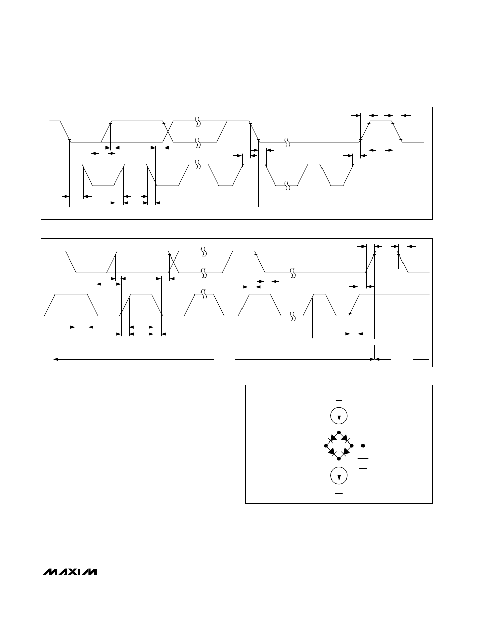
Figure 1a. F/S-Mode 2-Wire Serial-Interface Timing
V
DD
I
OL
I
OH
V
OUT
400pF
SDA
Figure 2. Load Circuits
t
HD.STA
t
SU.DAT
t
HIGH
t
FCL
t
HD.DAT
t
HD.STA
Sr
Sr
ACK
SCL
SDA
t
SU.STA
t
LOW
t
SU.STO
S
t
RCL
t
RCL1
HS-MODE
1
9
F/S-MODE
t
FDA
t
RDA
P
Figure 1b. HS-Mode 2-Wire Serial-Interface Timing