Table 9. monitor-mode setup data format, Table 11. delay settings, Table 12. lower and upper threshold data format – Rainbow Electronics MAX1364 User Manual
Page 19
clearing all alarms or by initiating an SMBus alert dur-
ing an alarm condition (see the SMBus Alert section).
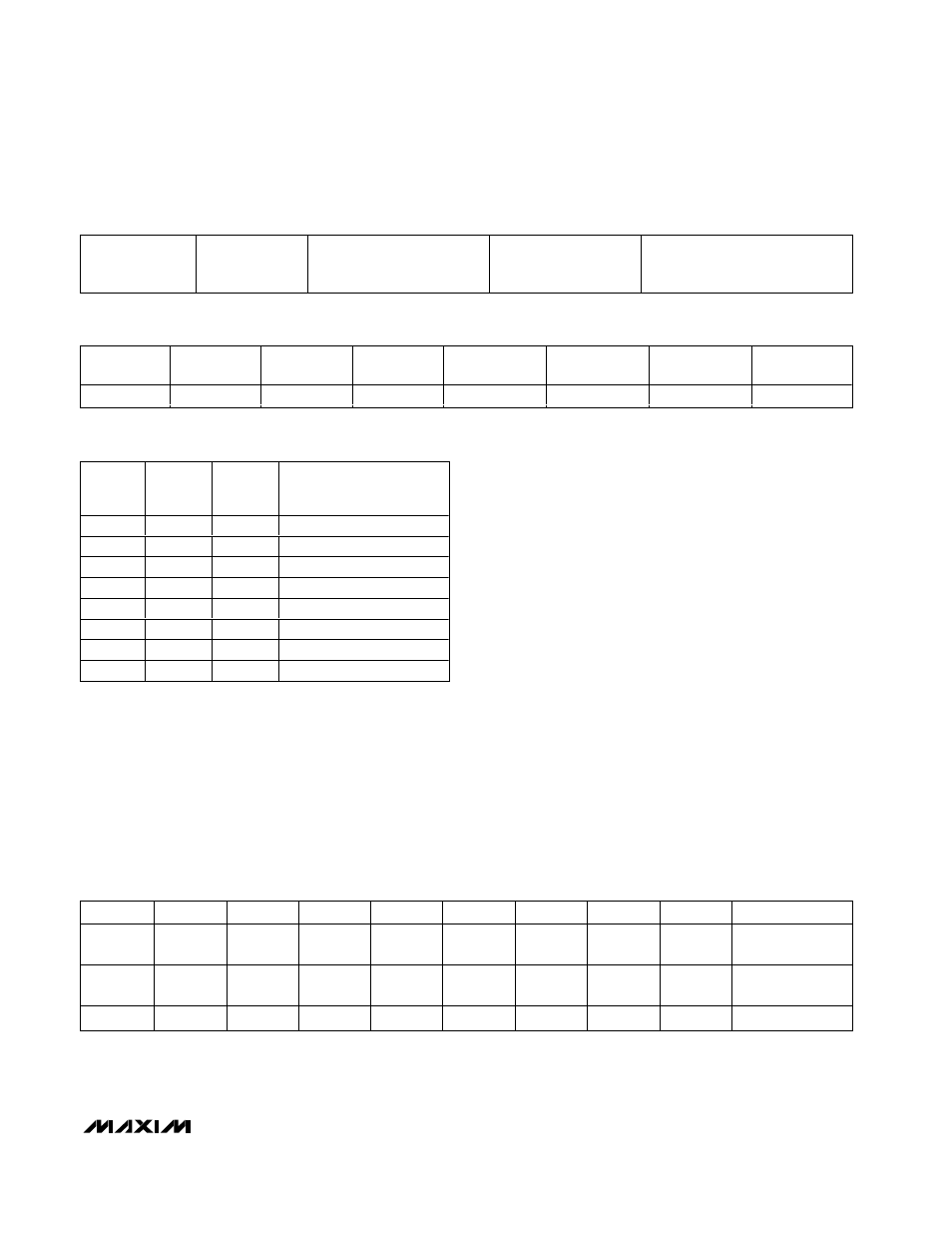
The Delay 2, Delay 1, Delay 0 bits set the speed of
monitoring by changing the delay between conver-
sions. Delay 2, 1, 0 = 000 sets the maximum possible
speed; 001 divides the maximum speed by ~2.
Increasing delay values further divides the previous
speed by two.
INT_EN controls the open-drain INT output. Set INT_EN
to 1 to enable the hardware interrupt. Set INT_EN to 0
to disable the hardware interrupt output. The INT output
tri-states when disabled or when there are no alarms.
The master can also poll the alarm status register at
any time to check the alarm status.
Repeat clocking channel threshold data up to the chan-
nel programmed by CS1 and CS0 (Table 12). For differ-
ential input mode, omit odd channels; the lower and
upper threshold data applies to channel pairs. There is
no need to clock in dummy data for odd (or even)
channels (Table 6).
To disable alarming on a specific channel, set the lower
threshold to 0x800 and the upper threshold to 0x7FF for
MAX1363/MAX1364
4-Channel, 12-Bit System Monitors with Programmable
Trip Window and SMBus Alert Response
______________________________________________________________________________________
19
Alarm reset, scan
speed, INT_EN ,
(8 bits)
AIN0 thresholds
(24 bits)
AIN1 thresholds
(skip if differential mode, or
CS1, CS0 < 1) (24 bits)
AIN2 thresholds (skip if
CS1, CS0 < 2)
(24 bits)
AIN3 thresholds (skip if differential
mode, or CS1, CS0 < 3)
(24 bits)
Table 9. Monitor-Mode Setup Data Format
RESET
ALARM CH 0
RESET
ALARM CH 1
RESET
ALARM CH 2
RESET
ALARM CH 3
DELAY 2
DELAY 1
DELAY 0
INT_EN
0/1
0/1
0/1
0/1
0/1
0/1
0/1
0/1
Table 10. Alarm Reset, Scan Speed Register, and INT_EN Data Format
DELAY 2 DELAY 1
DELAY 0
MONITOR-MODE
CONVERSION RATE
(ksps)
0
0
0
133.0*
0
0
1
66.5
0
1
0
33.3
0
1
1
16.6
1
0
0
8.3
1
0
1
4.2
1
1
0
2.0
1
1
1
1.0
Table 11. Delay Settings
*When using delay = [0,0,0] in internal reference mode and
AIN3/REF configured as a REF output, the MAX1363/MAX1364
may exhibit a code-dependent gain error due to insufficient
internal reference drive. Gain error caused by this phenomenon
is typically less than 1%FSR (0.1µF C
REF
) and increases with a
larger C
REF
. Avoid this gain error by using an external reference,
V
DD
, as a reference or use an internal reference with AIN3/REF
as an analog input (see Table 4). Alternatively, choose delay bits
other than [0,0,0] to lower the conversion rate.
BYTE
B7
B6
B5
B4
B3
B2
B1
B0
ACKNOWLEDGE
1
LT11
(MSB)
LT10
LT9
LT8
LT7
LT6
LT5
LT4
ACK
2
LT3
LT2
LT1
LT0 (LSB)
UT11
(MSB)
UT10
UT9
UT8
ACK
3
UT7
UT6
UT5
UT4
UT3
UT2
UT1
UT0 (LSB)
ACK
Table 12. Lower and Upper Threshold Data Format
X = Don’t care.
ACK = Acknowledge.