Table 1. i, C slave selection table – Rainbow Electronics MAX1364 User Manual
Page 13
unsuccessful data transfers. An unsuccessful data trans-
fer happens if a receiving device is busy or if a system
fault has occurred. In the event of an unsuccessful data
transfer, the bus master reattempts communication at a
later time.
Slave Address
The MAX1363/MAX1364 have a 7-bit I
2
C slave
address. The slave address is selected using A0. The
MAX1363/MAX1364 (EUB, MEUB, and LEUB) have
three base address options, allowing up to six devices
concurrently per I
2
C bus (see Table 1).
The MAX1363/MAX1364 continuously wait for a START
condition followed by its slave address. When the device
recognizes its slave address, it is ready to accept or
send data depending on the R/W bit (Figure 6).
HS I
2
C Mode
At power-up, the MAX1363/MAX1364 bus timing is set
for fast mode (F/S mode, up to 400kHz I
2
C clock), which
limits the conversion rate to approximately 22ksps.
Switch to high-speed mode (HS mode, up to 1.7MHz
I
2
C clock) to achieve conversion rates up to 94.4ksps.
The MAX1363/MAX1364 convert up to 133ksps in moni-
tor mode, regardless of I
2
C mode. If conversion results
are unread, I
2
C bandwidth limitations do not apply (see
the Monitor Mode section).
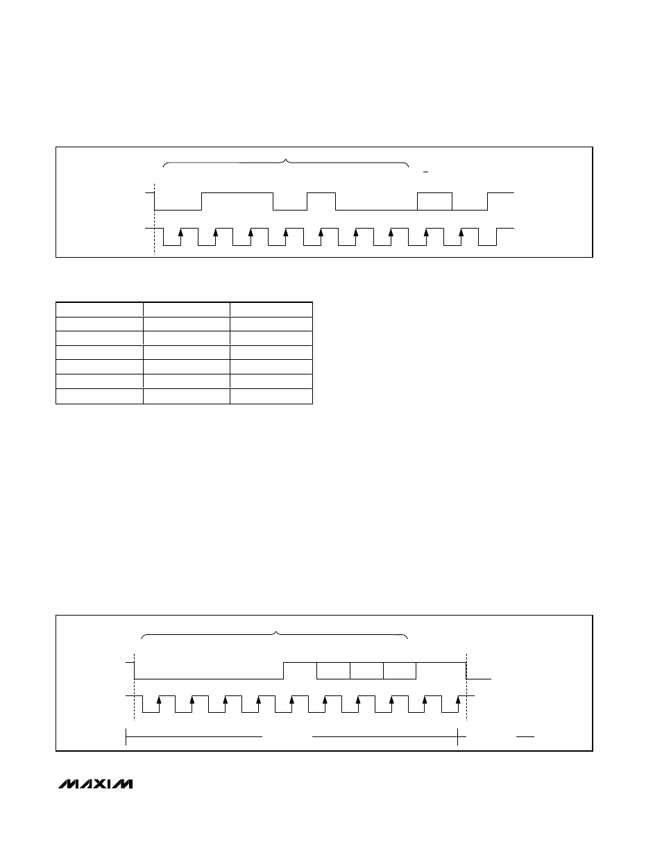
Select HS mode by addressing all devices on the bus
with the HS-mode master code 0000 1XXX (X = don’t
care). After successfully receiving the HS-mode master
code, the MAX1363/MAX1364 issue a NACK, allowing
SDA to be pulled high for one clock cycle (Figure 7).
After the NACK, the MAX1363/MAX1364 operate in HS
mode. Send a repeated START (Sr) followed by a slave
address to initiate HS-mode communication. If the mas-
ter generates a STOP condition, the MAX1363/
MAX1364 return to F/S mode. Use a repeated START
condition (Sr) in place of a STOP condition to leave the
bus active and the mode unchanged.
MAX1363/MAX1364
4-Channel, 12-Bit System Monitors with Programmable
Trip Window and SMBus Alert Response
______________________________________________________________________________________
13
0
1
1
1
0
0
0
R/W
ACK
SLAVE ADDRESS
S
SCL
SDA
1
2
3
4
5
6
7
8
9
Figure 6. MAX1363/MAX1364 Slave Address Byte
A0 STATE
SUFFIX
ADDRESS
Low
EUB
0110100
High
EUB
0110101
Low
LEUB
0110010
High
LEUB
0110011
Low
MEUB
0110110
High
MEUB
0110111
Table 1. I
2
C Slave Selection Table
0
0
0
1
0
X
X
X
NACK
HS-MODE MASTER CODE
SCL
SDA
S
Sr
F/S MODE
HS MODE
Figure 7. F/S-Mode to HS-Mode Transfer