Table 4. setup-byte format, Table 7. se/ dif and uni /bip table – Rainbow Electronics MAX1364 User Manual
Page 16
MAX1363/MAX1364
cycles begin with the bus master issuing a START
condition followed by 7 address bits and a read bit
(R/W = 1). After successfully receiving the address byte,
the MAX1363/MAX1364 (slave) issue an ACK. The master
then reads from the slave. (See Figures 10–13.)
The result is transmitted in 2 bytes. The 1st byte con-
sists of a leading 1 followed by a 2-bit binary channel
address tag, a 12/10 bit flag (1 for the MAX1363/
MAX1364), the first 4 bits of the data result, and the
expected ACK from the master. The 2nd byte contains
D7–D0. To read the next conversion result, issue an
ACK. To stop reading, issue a NACK.
4-Channel, 12-Bit System Monitors with Programmable
Trip Window and SMBus Alert Response
16
______________________________________________________________________________________
BIT
NAME
DESCRIPTION
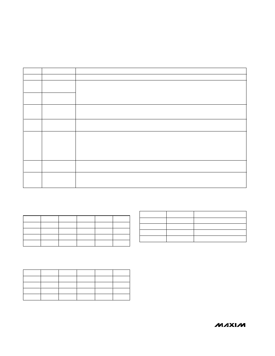
7 (MSB)
Setup
Setup byte always starts with 1.
6
REF/AIN SEL1
5
REF/AIN SEL0
When [0,0], REF/AIN3 = AIN3, REF = V
DD.
When [0,1], REF/AIN3 = REF, apply external reference to REF.
When [1,0], REF/AIN3 = AIN3, REF = internal reference.
When [1,1], REF/AIN3 = REF, REF = internal reference.
(Table 3)
4
INT REF Power
Down
1 = internal reference always powered up.
0 = internal reference always powered down.
(Table 3)
3
INT/EXT Clock
0 = internal clock.
1 = external clock (MAX1363/MAX1364 use the SCL clock for conversions).
2
UNI/BIP
0 = unipolar.
1 = bipolar.
Selects unipolar or bipolar conversion mode. In unipolar mode, analog signal in 0 to V
REF
range can
be converted. In differential bipolar mode, input signal can range from -V
REF
/ 2 to +V
REF
/ 2. When
single-ended mode is chosen, the SE/DIF bit of configuration byte overrides UNI/BIP, and
conversions are performed in unipolar mode.
1
Reset
1 = no action.
0 = resets INT and configuration register. Setup register and channel trip thresholds are unaffected.
0
Monitor Setup
0 = no action.
1 = extends writing up to 13 bytes (104 bits) of alarm reset mask. Scans speed selection and alarm
thresholds. See the Configuring Monitor Mode section.
Table 4. Setup-Byte Format*
*Power-on defaults: 0x82
CS1
CS0
CH0
CH1
CH2
CH3
0
0
+
0
1
+
1
0
+
1
1
+
Table 5. Channel Selection in Single-
Ended Mode (SE/
DIF
= 1)
CS1
CS0
CH0
CH1
CH2
CH3
0
0
+
-
0
1
-
+
1
0
+
-
1
1
-
+
Table 6. Channel Selection in Differential
Mode (SE/
DIF
= 0)
SE/
DIF
UNI
/BIP
MODE
0
0
Differential inputs, unipolar
0
1
Differential inputs, bipolar
1
0
Single-ended inputs, unipolar
1
1
Single-ended inputs, unipolar
Table 7. SE/
DIF
and
UNI
/BIP Table