Rainbow Electronics MAX1364 User Manual
Page 18
MAX1363/MAX1364
When the MAX1363/MAX1364 receive a NACK, they
release SDA allowing the master to generate a STOP or
a repeated START condition.
Monitor Mode
Monitor-Mode Overview
The MAX1363/MAX1364 automatically monitor up to four
input channels. For systems with limited I
2
C bandwidth,
monitor mode allows the µC to set a window by
programming lower and upper thresholds during initial-
ization, and only intervening if the MAX1363/MAX1364
detect an alarm condition. This allows an interrupt-driven
approach as an alternative to continuously polling the
ADC with the µC. Monitor mode reduces processor over-
head and conserves I
2
C bandwidth.
The following shows an example of events in
monitor mode:
1) Fault condition(s) detected, INT asserted.
2) Host µC services interrupt and sends SMBus alert to
identify the alarming device. The MAX1363/
MAX1364 respond with the I
2
C slave address, pend-
ing arbitration rules. (See the SMBus Alert section.)
3) The MAX1363/MAX1364 release the INT.
4) Host µC reads the alarm-status register, latched-
fault register, and current-conversion results to
determine the alarming channel(s) and course
of action.
5) Host µC services alarm(s); adjusts system parame-
ters as needed and/or adjusts lower and upper
thresholds.
6) Host µC resets the alarming channel. See the
Configuring Monitor Mode section.
7) Monitor mode resumes.
8) If there is still an active fault, the device asserts INT
again. See step 1.
Writing SCAN1 and SCAN0 bits = [1,0] in the configura-
tion byte activates monitor mode. The MAX1363/
MAX1364 scan from channels 0 up to the channel
selected by [CS1:CS0] at a rate determined by the
scan delay bits. The MAX1363/MAX1364 compare the
conversion results with the lower and upper thresholds
for each channel. When any conversion exceeds the
threshold, the MAX1363/MAX1364 assert an interrupt
by pulling INT low (if enabled). The MAX1363/
MAX1364 set the corresponding flag bit in the alarm-
status register and write conversion results to the
latched-fault register to record the event causing the
alarm condition.
INT active state is randomly delayed with respect to the
conversion. Depending on the number of channels
scanned and the position in the channel scan sequence,
the maximum possible delay for asserting INT is five
conversion periods (37.5µs typ, Delay = 0,0,0).
Configuring Monitor Mode
To write monitoring setup data, set the monitor-setup bit
(bit 0 in setup byte) to 1 to extend writing up to 104 bits
(13 bytes) of monitoring setup data. The number of bits
written to the MAX1363/MAX1364 depends on whether
the part is in single-ended or differential mode and
whether the upper channel limit is set by [CS1:CS0]
(Table 9).
Terminate writing at any time by using a STOP or
repeated START condition. Previous monitoring setup
data not overwritten remains valid.
A 1 written to the reset alarm CH_ clears the alarm, oth-
erwise no action occurs (Table 10). Deassert INT by
4-Channel, 12-Bit System Monitors with Programmable
Trip Window and SMBus Alert Response
18
______________________________________________________________________________________
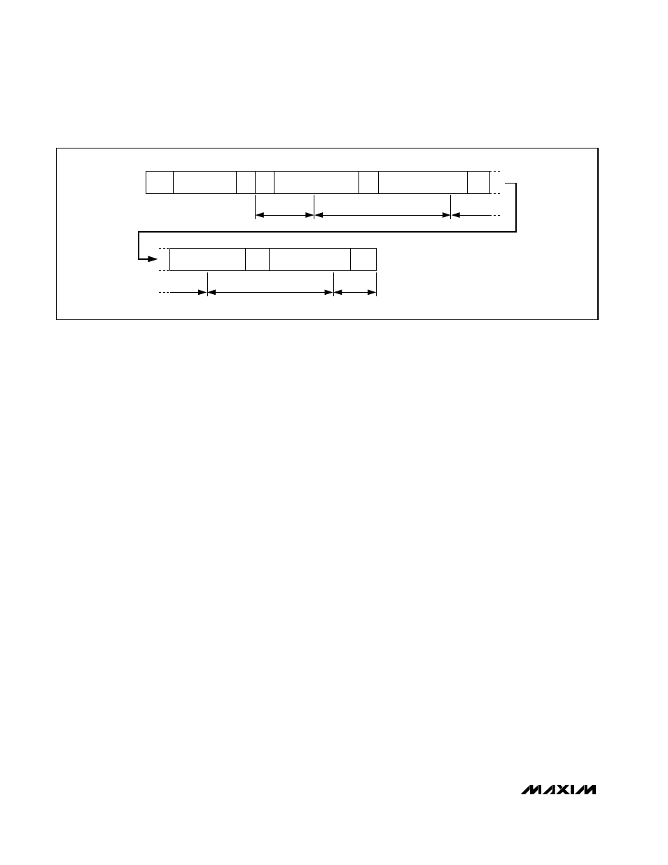
ACK
ACK
1, CH ADD, 10b/12b,
RESULT (4 MSBs)
RESULT N (8 LSBs)
t
ACQ
t
ACQ
CONVERSION 1
t
ACQ
t
ACQ
CONVERSION N
START
ADDRESS
FROM THE MASTER
1, CH ADD, 10b/12b
RESULT (4 MSBs)
RESULT (8 LSBs)
1
ACK
ACK
ACK
Figure 13. Example of Scan-Mode Conversions Using the External Clock, SCAN = 0,0 and 0,1