Ac electrical characteristics, Dc electrical characteristics – Rainbow Electronics LM96000 User Manual
Page 5
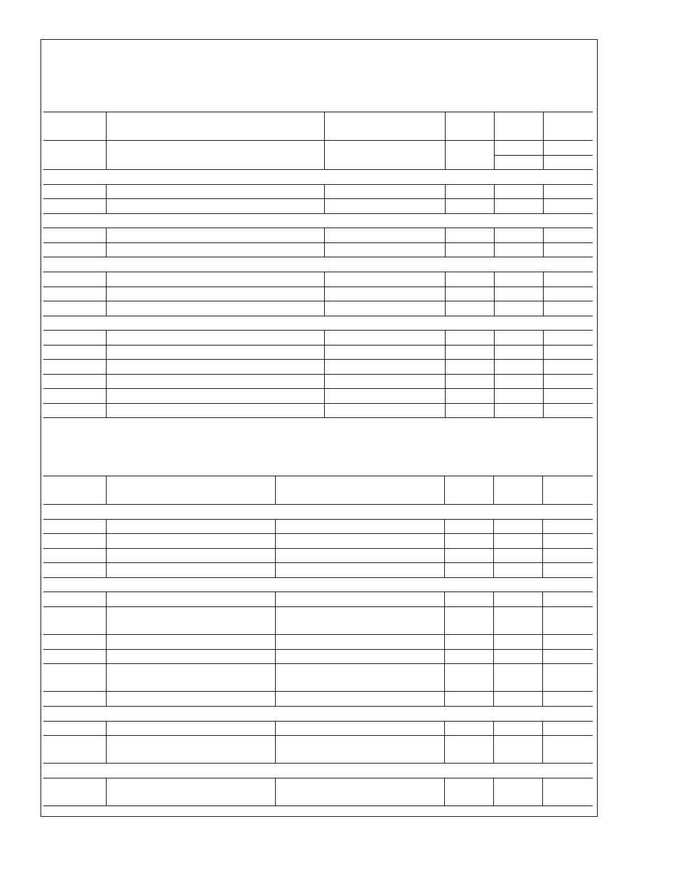
DC Electrical Characteristics
(Continued)
The following specifications apply for V+ = 3.0V to 3.6V, and all analog input source impedance R
S
= 50
Ω unless otherwise
specified in conditions. Boldface limits apply for T
A
= T
J
over T
MIN
=0˚C to T
MAX
=85˚C; all other limits T
A
=T
J
= 25˚C. T
A
is
the ambient temperature of the LM96000; T
J
is the junction temperature of the LM96000; T
D
is the thermal diode junction tem-
perature.
Symbol
Parameter
Conditions
Typical
Limits
Units
(Limits)
Input Resistance, all analog inputs
210
140
k
Ω (min)
400
k
Ω (max)
DIGITAL OUTPUT: PWM1, PWM2, PWM3, XTESTOUT
I
OL
Logic Low Sink Current
V
OL
=0.4V
8
mA (min)
V
OL
Logic Low Level
I
OUT
= +8 mA
0.4
V (max)
SMBUS OPEN-DRAIN OUTPUT: SMBDAT
V
OL
Logic Low Output Voltage
I
OUT
= +4 mA
0.4V
V (max)
I
OH
High Level Output Current
V
OUT
= V+
0.1
10
µA (max)
SMBUS INPUTS: SMBCLK. SMBDAT
V
IH
Logic Input High Voltage
2.1
V (min)
V
IL
Logic Input Low Voltage
0.8
V (max)
V
HYST
Logic Input Hysteresis Voltage
300
mV
DIGITAL INPUTS: ALL
V
IH
Logic Input High Voltage
2.1
V (min)
V
IL
Logic Input Low Voltage
0.8
V (max)
V
TH
Logic Input Threshold Voltage
1.5
V
I
IH
Logic High Input Current
V
IN
= V+
0.005
10
µA (max)
I
IL
Logic Low Input Current
V
IN
= GND
−0.005
−10
µA (max)
C
IN
Digital Input Capacitance
20
pF
AC Electrical Characteristics
The following specifications apply for V+ = 3.0V to 3.6V unless otherwise specified in conditions. Boldface limits apply for T
A
= T
J
over T
MIN
=0˚C to T
MAX
=85˚C; all other limits T
A
=T
J
= 25˚C.
Symbol
Parameter
Conditions
Typical
Limits
Units
(Limits)
TACHOMETER ACCURACY
Fan Count Accuracy
±
10
% (max)
Fan Full-Scale Count
65536
(max)
Fan Counter Clock Frequency
90
kHz
Fan Count Conversion Time
0.7
1.4
sec (max)
FAN PWM OUTPUT
Frequency Setting Accuracy
±
10
% (max)
Frequency Range
10
30
Hz
kHz
Duty-Cycle Range
Low frequency range
0 to 100
% (max)
Duty-Cycle Resolution (8-bits)
0.390625
%
Spin-Up Time Interval Range
100
4000
ms ms
Spin-Up Time Interval Accuracy
±
10
% (max)
SPIKE SMOOTHING FILTER
Time Interval Deviation
±
10
% (max)
Time Interval Range
35
0.8
sec
sec
SMBUS TIMING CHARACTERISTICS
f
SMB
SMBus Operating Frequency
10
100
kHz (min)
kHz (max)
LM96000
www.national.com
5