Rainbow Electronics LM96000 User Manual
General description, Features, Key specifications
LM96000
Hardware Monitor with Integrated Fan Control
General Description
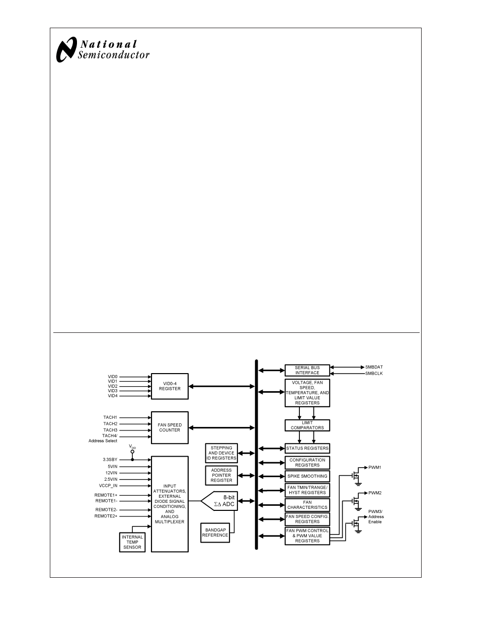
The LM96000, hardware monitor, has a two wire digital
interface compatible with SMBus 2.0. Using an 8-bit
Σ∆
ADC, the LM96000 measures:
– the temperature of two remote diode connected transis-
tors as well as its own die
– the VCCP, 2.5V, 3.3VSBY, 5.0V, and 12V supplies (in-
ternal scaling resistors).
To set fan speed, the LM96000 has three PWM outputs that
are each controlled by one of three temperature zones. High
and low PWM frequency ranges are supported. The
LM96000 includes a digital filter that can be invoked to
smooth temperature readings for better control of fan speed.
The LM96000 has four tachometer inputs to measure fan
speed. Limit and status registers for all measured values are
included.
Features
n
2-wire, SMBus 2.0 compliant, serial digital interface
n
8-bit
Σ∆ ADC
n
Monitors VCCP, 2.5V, 3.3 VSBY, 5.0V, and 12V
motherboard/processor supplies
n
Monitors 2 remote thermal diodes
n
Programmable autonomous fan control based on
temperature readings
n
Noise filtering of temperature reading for fan control
n
1.0˚C digital temperature sensor resolution
n
3 PWM fan speed control outputs
n
Provides high and low PWM frequency ranges
n
4 fan tachometer inputs
n
Monitors 5 VID control lines
n
24-pin TSSOP package
n
XOR-tree test mode
Key Specifications
n
Voltage Measurement Accuracy
±
2% FS (max)
n
Resolution
8-bits, 1˚C
n
Temperature Sensor Accuracy
±
3˚C (max)
n
Temperature Range
— LM96000 Operational
0˚C to +85˚C
— Remote Temp Accuracy
0˚C to +125˚C
n
Power Supply Voltage
+3.0V to +3.6V
n
Power Supply Current
0.53 mA
Applications
n
Desktop PC
n
Microprocessor based equipment
(e.g. Base-stations, Routers, ATMs, Point of Sales)
Block Diagram
20084601
November 2004
LM96000
Hardware
Monitor
with
Integrated
Fan
Control
© 2004 National Semiconductor Corporation
DS200846
www.national.com
Document Outline
- LM96000
- General Description
- Features
- Key Specifications
- Applications
- Block Diagram
- Connection Diagram
- Pin Descriptions
- Absolute Maximum Ratings
- Operating Ratings (Notes , )
- DC Electrical Characteristics
- AC Electrical Characteristics
- Functional Description
- 1.0 SMBUS
- 2.0 FAN REGISTER DEVICE SET-UP
- 3.0 AUTO FAN CONTROL OPERATING MODE
- 4.0 REGISTER SET
- 4.1 Register 20-24h: Voltage Reading
- 4.2 Register 25-27h: Temperature Reading
- 4.3 Register 28-2Fh: Fan Tachometer Reading
- 4.4 Register 30-32h: Current PWM Duty
- 4.5 Register 3Eh: Company ID
- 4.6 Register 3Fh: Version/Stepping
- 4.7 Register 40h: Ready/Lock/Start/Override
- 4.8 Register 41h: Interrupt Status Register 1
- 4.9 Register 42h: Interrupt Status Register 2
- 4.10 Register 43h: VID
- 4.11 Registers 44-4Dh: Voltage Limit Registers
- 4.12 Registers 4E-53h: Temperature Limit Registers
- 4.13 Registers 54-5Bh: Fan Tachometer Low Limit
- 4.14 Registers 5C-5Eh: Fan Configuration
- 4.15 Registers 5F-61h: Auto Fan Speed Range, PWM Frequency
- 4.16 Registers 62, 63h: Min/Off, Spike Smoothing
- 4.17 Registers 64-66h: Minimum PWM Duty Cycle
- 4.18 Registers 67-69h: Temperature Limit
- 4.19 Registers 6A-6Ch: Absolute Temperature Limit
- 4.20 Registers 6D-6Eh: Zone Hysteresis Registers
- 4.21 Register 6Fh: Test Register
- 4.22 Registers 70-7Fh: Vendor Specific Registers
- 4.23 Undefined Registers
- 5.0 XOR TEST MODE
- Applications Information
- Physical Dimensions