Table 7. spike smoothing, Functional description – Rainbow Electronics LM96000 User Manual
Page 21
Functional Description
(Continued)
Register
Address
Read/
Write
Register
Name
Bit 7
(MSB)
Bit 6
Bit 5
Bit 4 Bit 3
Bit 2
Bit 1
Bit 0
(LSB)
Default
Value
Lock?
63h
R/W
Zone2, Zone3 Spike Smoothing
ZN2E
ZN2-2 ZN2-1 ZN2-0 ZN3E ZN3-2 ZN3-1 ZN3-0 00h
U
The Off/Min Bits [7:5] specify whether the duty cycle will be 0% or Minimum Fan Duty when the measured temperature falls below
the Temperature LIMIT register setting (see table below). OFF1 applies to fan 1, OFF2 applies to fan 2, and OFF3 applies to fan
3.
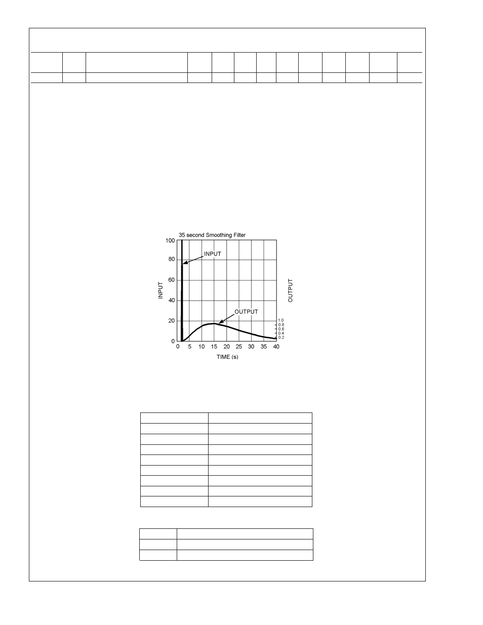
If the Remote1 or Remote2 pins are connected to a processor or chipset, instantaneous temperature spikes may be sampled by
the LM96000. If these spikes are not ignored, the CPU fan (if connected to LM96000) may turn on prematurely and produce
unpleasant noise. For this reason, any zone that is connected to a chipset or processor should have spike smoothing enabled.
When spike smoothing is enabled, the temperature reading registers will still reflect the current value of the temperature — not
the ‘smoothed out’ value.
ZN1E, ZN2E, and ZN3E enable temperature smoothing for zones 1, 2, and 3 respectively.
ZN1-2, ZN1-1, and ZN1-0 control smoothing time for Zone 1.
ZN2-2, ZN2-1, and ZN2-0 control smoothing time for Zone 2.
ZN3-2, ZN3-1, and ZN3-0 control smoothing time for Zone 3.
These registers become ready only when the Ready/Lock/Start/Override register Lock bit is set. Any further attempts to write to
these registers shall have no effect.
TABLE 7. Spike Smoothing
ZN-X[2:0]
Spike Smoothed Over
000
35 seconds
001
17.6 seconds
010
11.8 seconds
011
7.0 seconds
100
4.4 seconds
101
3.0 seconds
110
1.6 seconds
111
.8 seconds
TABLE 8. PWM Output Below Limit Depending on Value of Off/Min
Off/Min
PWM Action
0
At 0% duty below LIMIT
1
At Min PWM Duty below LIMIT
20084607
FIGURE 2. What LM96000 Auto Fan Control Sees With and Without Spike Smoothing
LM96000
www.national.com
21