8 register 41h: interrupt status register 1, Functional description – Rainbow Electronics LM96000 User Manual
Page 14
Functional Description
(Continued)
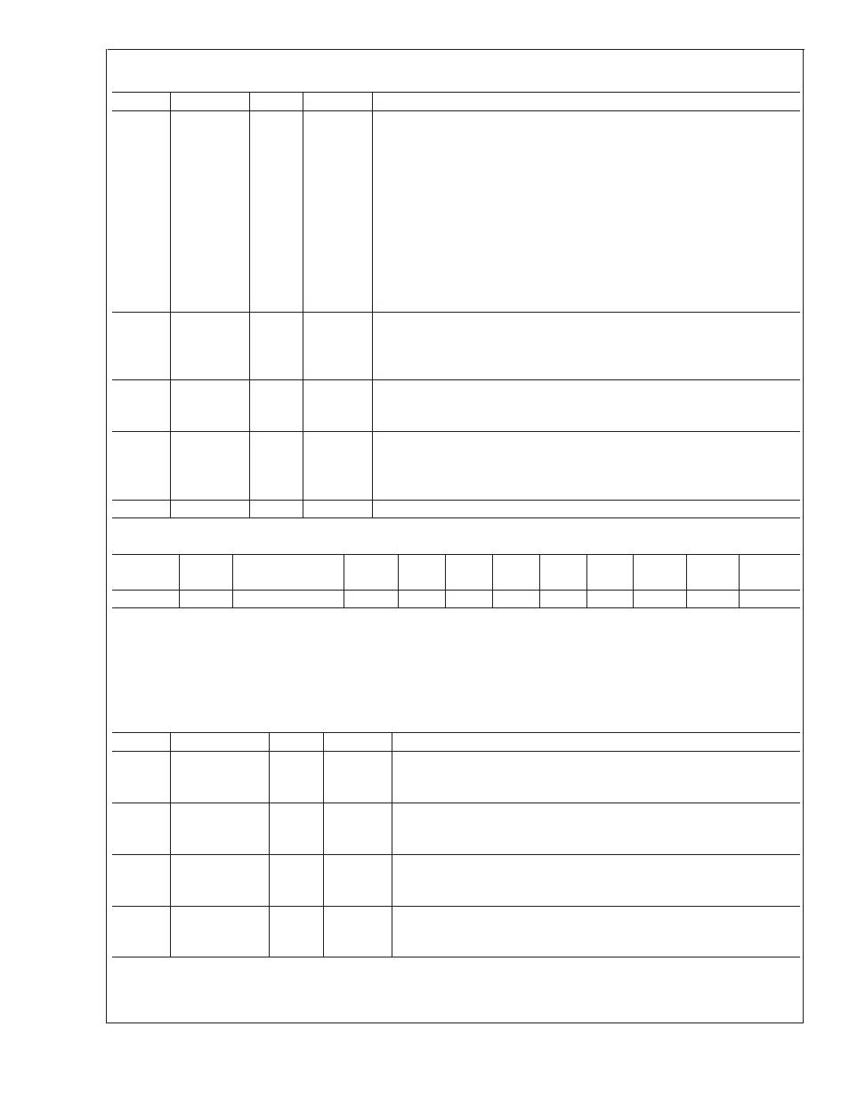
Bit
Name
R/W
Default
Description
0
START
R/W
0
When software writes a 1 to this bit, the LM96000 fan monitoring and PWM
output control functions will use the values set in the fan control limit and
parameter registers (address 5Ch through 6Eh). Before this bit is set, the
LM96000 will not update the used register values, the default values will
remain in effect. Whenever this bit is set to 0, the LM96000 fan monitoring and
PWM output control functions use the default fan limits and parameters,
regardless of the current values in the limit and parameter registers (5C
through 6Eh). The LM96000 will preserve the values currently stored in the
limit and parameter registers when this bit is set or cleared. This bit is not
effected by the state of the Lock bit.
It is expected that all limit and parameter registers will be set by BIOS or
application software prior to setting this bit.
1
LOCK
R/W
0
Setting this bit to 1 locks specified limit and parameter registers. Once this bit
is set, limit and parameter registers become read only and will remain locked
until the device is powered off. This register bit becomes read only once it is
set.
2
READY
R
0
The LM96000 sets this bit automatically after the part is fully powered up, has
completed the power-up-reset process, and after all A/D converters are
properly functioning.
3
OVRID
R/W
If this bit is set to 1, all PWM outputs will go to 100% duty cycle regardless of
whether or not the lock bit is set. The OVRID bit has precedence over the
disabled mode. Therefore, when OVRID is set the PWM will go to 100% even
if the PWM is in the disabled mode.
4–7
Reserved
R
0
Reserved
4.8 Register 41h: Interrupt Status Register 1
Register
Address
Read/
Write
Register
Name
Bit 7
(MSB)
Bit 6
Bit 5
Bit 4
Bit 3
Bit 2
Bit 1
Bit 0
(LSB)
Default
Value
41h
R
Interrupt Status 1
ERR
ZN3
ZN2
ZN1
5V
3.3V
VCCP
2.5V
00h
The Interrupt Status Register 1 bits will be automatically set, by the LM96000, whenever a fault condition is detected. A fault
condition is detected whenever a measured value is outside the window set by its limit registers. ZN3 and ZN1 bits will be set
when a diode fault condition, such as a disconect or short, is detected. More than one fault may be indicated in the interrupt
register when read. This register will hold a set bit(s) until the event is read by software. The contents of this register will be
cleared (set to 0) automatically by the LM96000 after it is read by software, if the fault condition is no longer exists. Once set, the
Interrupt Status Register 1 bits will remain set until a read event occurs, even if the fault condition no longer exists
This register is read only — a write to this register has no effect.
Bit
Name
R/W
Default
Description
0
2.5V_Error
R
0
The LM96000 automatically sets this bit to 1 when the 2.5V input voltage
is less than or equal to the limit set in the 2.5V Low Limit register or
greater than the limit set in the 2.5V High Limit register.
1
VCCP_Error
R
0
The LM96000 automatically sets this bit to 1 when the VCCP input voltage
is less than or equal to the limit set in the VCCP Low Limit register or
greater than the limit set in the VCCP High Limit register.
2
3.3V_Error
R
0
The LM96000 automatically sets this bit to 1 when the 3.3V input voltage
is less than or equal to the limit set in the 3.3V Low Limit register or
greater than the limit set in the 3.3V High Limit register.
3
5V_Error
R
0
The LM96000 automatically sets this bit to 1 when the 5V input voltage is
less than or equal to the limit set in the 5V Low Limit register or greater
than the limit set in the 5V High Limit register.
LM96000
www.national.com
14