Table 12. hysteresis settings, 21 register 6fh: test register, 22 registers 70-7fh: vendor specific registers – Rainbow Electronics LM96000 User Manual
Page 25: 1 register 74h: tachometer monitor mode, Functional description
Functional Description
(Continued)
– The fan will remain on, at Fan PWM Minimum, until the temperature goes a certain amount below Fan Temp Limit.
– The Hysteresis registers control this amount. See below table for details.
These registers become Read Only when the Ready/Lock/Start/Override register Lock bit is set. Any further attempts to write to
thses registers shall have no effect. After power up the default value is used whenever the Ready/Lock/Start/Override register
Start bit is cleared even though modifications to this register are possible.
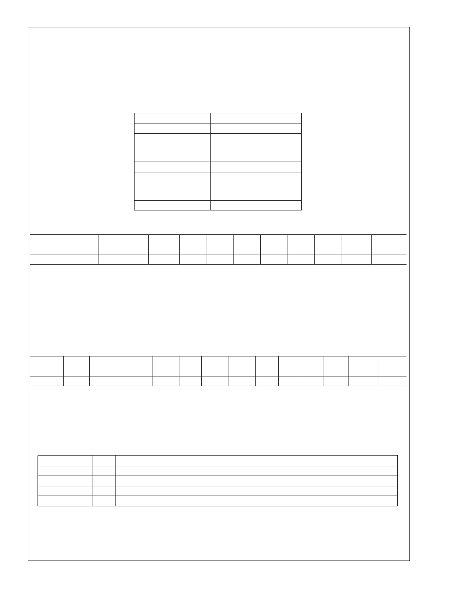
TABLE 12. Hysteresis Settings
Setting
HYSTERESIS
0h
0˚C
.
.
.
.
.
.
5h
5˚C
.
.
.
.
.
.
Fh
15˚C
4.21 Register 6Fh: Test Register
Register
Address
Read/
Write
Register
Name
Bit 7
(MSB)
Bit 6
Bit 5
Bit 4
Bit 3
Bit 2
Bit 1
Bit 0
(LSB)
Default
Value
6Fh
R/W
Test Register
RES
RES
RES
RES
RES
RES
RES
XEN
00h
If the XEN bit is set high, the part will be placed into XOR tree test mode. Clearing the bit (writing a 0 to the XEN bit) brings the
part out of XOR tree test mode.
This register becomes Read Only when the Ready/Lock/Start/Override register Lock bit is set. Any further attempts to write to this
registers shall have no effect. After power up the default value is used whenever the Ready/Lock/Start/Override register Start bit
is cleared even though modifications to this register are possible.
4.22 Registers 70-7Fh: Vendor Specific Registers
These registers are for vendor specific features, including test registers. They will not default to a specific value on power up.
4.22.1 Register 74h: Tachometer Monitor Mode
Register
Address
Read/
Write
Register
Name
Bit 7
(MSb)
Bit 6
Bit 5
Bit 4
Bit 3
Bit 2
Bit 1
Bit 0
(LSb)
Default
Value
Lock?
74h
R/W
Tach Monitor Mode
RES
RES
T3/4-1
T3/4-0
T2-1
T2-0
T1-1
T1-0
00h
Each fan TACH input has 4 possible modes of operation when using the low frequency range for the PWM outputs. Mode 0 is the
only mode that is available when using the high frequecy range for the PWM outputs. The modes for TACH3 and TACH4 share
control bits T3/4-[1:0]; TACH2 is controlled by T2-[1:0]; TACH1 is controlled by T1-[1:0]. The result reported in all modes is based
on 2 pulses per revolution. In order for modes 2 and 3 to function properly it is required that the:
PWM1 output must control the fan that has it’s tachometer output connected to the TACH1 LM96000 input.
PWM2 output must control the fan that has it’s tachometer output connected to the TACH2 LM96000 input.
PWM3 output must control the fans that have their tachometer outputs connected to the TACH3 or TACH4 LM96000 inputs.
Setting (Tn[1:0]) Mode Function
00
0
Traditional tach input monitor, false readings when under minimum detctable RPM
01
1
Traditional tach input monitor, FFFFh reading when under minimum detectable RPM
10
2
Most accurate readings, FFFFh reading when under minimum detectable RPM
11
3
Least effect on programmed PWM of Fan, FFFFh reading when under minimum detectable RPM
•
Mode 0: This mode uses the conventional method for fan tachometer pulse detection and does not include any circuitry to
compensate for PWM Fan drive. This mode should be used when PWM drive is not used to power the fan. This mode may
report a false RPM reading when under minimum detectable RPM as shown in the following table.
•
Mode 1: This mode uses the conventional method for fan tach detection. The reading will be FFFFh if it is below minimum
detectable RPM.
LM96000
www.national.com
25