Table 6. register setting vs pwm frequency, 16 registers 62, 63h: min/off, spike smoothing, Functional description – Rainbow Electronics LM96000 User Manual
Page 20
Functional Description
(Continued)
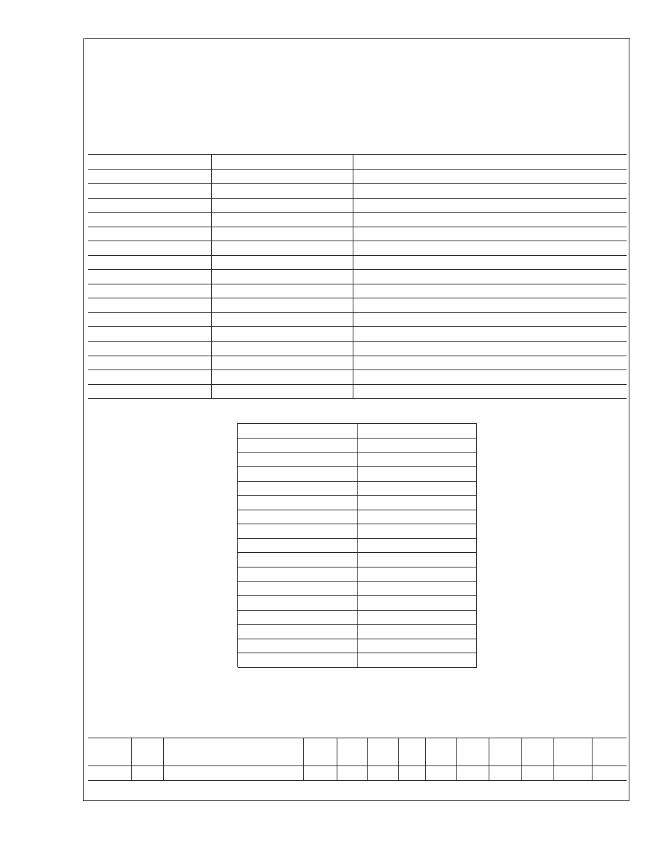
Above (Zone 1 Fan Temp Limit) + (Zone 1 Range), the duty cycle will be 100%.
PWM frequency bits [3:0]
The PWM frequency bits [3:0] determine the PWM frequency for the fan.The LM96000 has high and low frequency ranges for the
PWM outputs, that are controlled by the HLFRQ bit.
PWM Frequency Selection (Default = 0011 = 30.04 Hz).
TABLE 6. Register Setting vs PWM Frequency
HLFRQ
Freq [2:0]
PWM Frequency
0
000
10.01 Hz
0
001
15.02 Hz
0
010
23.14 Hz
0
011
30.04 Hz
0
100
38.16 Hz
0
101
47.06 Hz
0
110
61.38 Hz
0
111
94.12 Hz
1
000
22.5 kHz
1
001
24 kHz
1
010
25.7 kHz
1
011
25.7 kHz
1
100
27.7 kHz
1
101
27.7 kHz
1
110
30 kHz
1
111
30 kHz
Range Selection RAN [3:0]
RAN [3:0]
Range (˚C)
0000
2
0001
2.5
0010
3.33
0011
4
0100
5
0101
6.67
0110
8
0111
10
1000
13.33
1001
16
1010
20
1011
26.67
1100
32
1101
40
1110
53.33
1111
80
This register becomes Read Only when the Ready/Lock/Start/Override register Lock bit is set. Any further attempts to write to this
register shall have no effect. After power up the default value is used whenever the Ready/Lock/Start/Override register Start bit
is cleared even though modifications to this register are possible.
4.16 Registers 62, 63h: Min/Off, Spike Smoothing
Register
Address
Read/
Write
Register
Name
Bit 7
(MSB)
Bit 6
Bit 5
Bit 4 Bit 3
Bit 2
Bit 1
Bit 0
(LSB)
Default
Value
Lock?
62h
R/W
Min/Off, Zone1 Spike Smoothing OFF3
OFF2 OFF1 RES
ZN1E ZN1-2 ZN1-1 ZN1-0 00h
U
LM96000
www.national.com
20