Table 5. fan spin-up register, Figure 1. fan activity above fan temp limit, Functional description – Rainbow Electronics LM96000 User Manual
Page 19
Functional Description
(Continued)
TABLE 5. Fan Spin-Up Register
SPIN[2:0]
Spin Up Time
000
0 sec
001
100 ms
010
250 ms
011
400 ms
100
700 ms
101
1000 ms
110
2000 ms
111
4000 ms
4.15 Registers 5F-61h: Auto Fan Speed Range, PWM Frequency
Register
Address
Read/
Write
Register
Name
Bit 7
(MSB)
Bit 6
Bit 5
Bit 4
Bit 3
Bit 2
Bit 1
Bit 0
(LSB)
Default
Value
Lock?
5Fh
R/W
Zone1 Range/Fan1
Frequency
RAN3
RAN2
RAN1
RAN0
HLFRQ
FRQ2
FRQ1
FRQ0
C4h
U
60h
R/W
Zone2 Range/Fan2
Frequency
RAN3
RAN2
RAN1
RAN0
HLFRQ
FRQ2
FRQ1
FRQ0
C4h
U
61h
R/W
Zone3 Range/Fan3
Frequency
RAN3
RAN2
RAN1
RAN0
HLFRQ
FRQ2
FRQ1
FRQ0
C4h
U
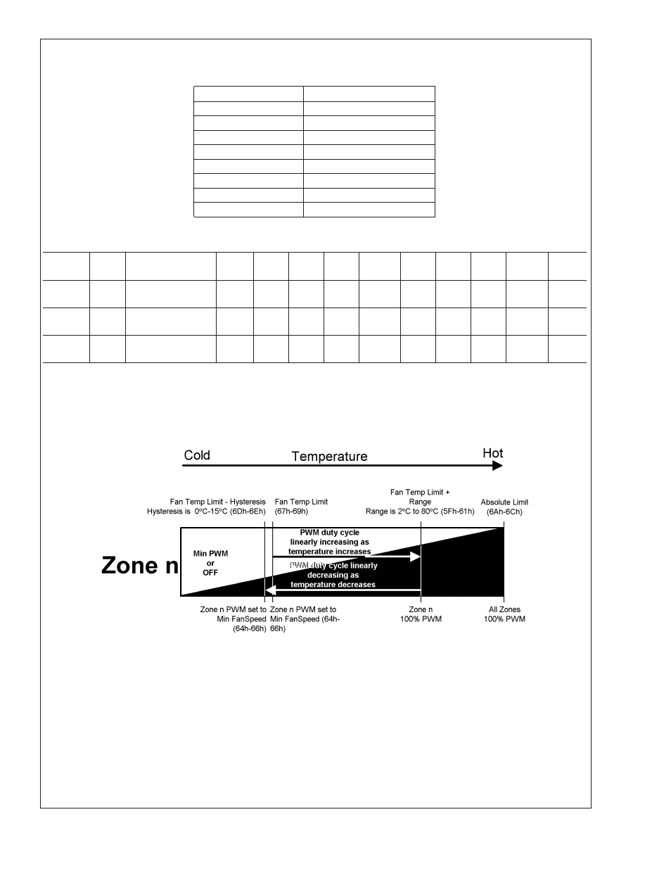
In Auto Fan Mode, when the temperature for a zone is above the Temperature Limit (Registers 67-69h) and below its Absolute
Temperature Limit (Registers 6A-6Ch), the speed of a fan assigned to that zone is determined as follows.
When the temperature reaches the Fan Temp Limit for a zone, the PWM output assigned to that zone will be Fan PWM Minimum.
Between Fan Temp Limit and (Fan Temp Limit + Range), the PWM duty cycle will increase linearly according to the temperature
as shown in the figure below. The PWM duty cycle will be 100% at (Fan Temp Limit + Range).
Example for PWM1 assigned to Zone 1:
– Zone 1 Fan Temp Limit (Register 67h) is set to 50˚C (32h).
– Range (Register 5Fh) is set to 8˚C (6xh).
– Fan 1 PWM Minimum (Register 64h) is set to 50% (32h).
In this case, the PWM1 duty cycle will be 50% at 50˚C.
Since (Zone 1 Fan Temp Limit) + (Zone 1 Range) = 50˚C + 8˚C = 58˚C, the fan will run at 100% duty cycle when the temperature
of the Zone 1 sensor reaches 58˚C.
Since the midpoint of the fan control range is 54˚C, and the median duty cycle is 75% (Halfway between the PWM Minimum and
100%), PWM1 duty cycle would be 75% at 54˚C.
20084606
FIGURE 1. Fan Activity above Fan Temp Limit
LM96000
www.national.com
19