10 register 43h: vid, 11 registers 44-4dh: voltage limit registers, Table 2. voltage limits vs register setting – Rainbow Electronics LM96000 User Manual
Page 16: 12 registers 4e-53h: temperature limit registers, Functional description
Functional Description
(Continued)
Bit
Name
R/W
Default
Description
7
Remote Diode
2 Fault
R
0
The LM96000 automatically sets this bit to 1 when there is either a short
or open circuit fault on the Remote2+ or Remote2− thermal diode input
pins. A diode fault will also set bit 6, Diode 2 Zone Limit bit, of Interrupt
Status Register 1.
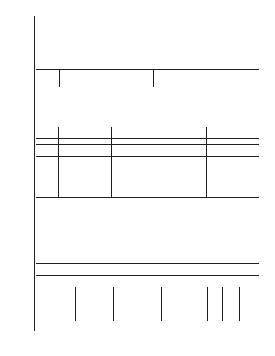
4.10 Register 43h: VID
Register
Address
Read/
Write
Register
Name
Bit 7
(MSB)
Bit 6
Bit 5
Bit 4
Bit 3
Bit 2
Bit 1
Bit 0
(LSB)
Default
Value
43h
R
VID0–4
RES
RES
RES
VID4
VID3
VID2
VID1
VID0
The VID register contains the values of LM96000 VID0–VID4 input pins. This register indicates the status of the VID lines that
interconnect the processor to the Voltage Regulator Module (VRM). Software uses the information in this register to determine the
voltage that the processor is designed to operate at. With this information, software can then dynamically determine the correct
values to place in the VCCP Low Limit and VCCP High Limit registers.
This register is read only — a write to this register has no effect.
4.11 Registers 44-4Dh: Voltage Limit Registers
Register
Address
Read/
Write
Register
Name
Bit 7
(MSB)
Bit 6
Bit 5
Bit 4
Bit 3
Bit 2
Bit 1
Bit 0
(LSB)
Default
Value
44h
R/W
2.5V Low Limit
7
6
5
4
3
2
1
0
00h
45h
R/W
2.5V High Limit
7
6
5
4
3
2
1
0
FFh
46h
R/W
VCCP Low Limit
7
6
5
4
3
2
1
0
00h
47h
R/W
VCCP High Limit
7
6
5
4
3
2
1
0
FFh
48h
R/W
3.3V Low Limit
7
6
5
4
3
2
1
0
00h
49h
R/W
3.3V High Limit
7
6
5
4
3
2
1
0
FFh
4Ah
R/W
5V Low Limit
7
6
5
4
3
2
1
0
00h
4Bh
R/W
5V High Limit
7
6
5
4
3
2
1
0
FFh
4Ch
R/W
12V Low Limit
7
6
5
4
3
2
1
0
00h
4Dh
R/W
12V High Limit
7
6
5
4
3
2
1
0
FFh
If a voltage input either exceeds the value set in the voltage high limit register or falls below the value set in the voltage low limit
register, the corresponding bit will be set automatically by the LM96000 in the interrupt status registers (41-42h). Voltages are
presented in the registers at
3
⁄
4
full scale for the nominal voltage, meaning that at nominal voltage, each input will be C0h, as
shown in Table 2.
Setting the Ready/Lock/Start/Override register Lock bit has no effect on these registers.
TABLE 2. Voltage Limits vs Register Setting
Input
Nominal
Voltage
Register Setting at
Nominal Voltage
Maximum
Voltage
Register Reading at
Maximum Voltage
Minimum
Voltage
Register Reading at
Minimum Voltage
2.5V
2.5V
C0h
3.32V
FFh
0V
00h
VCCP
2.25V
C0h
3.00V
FFh
0V
00h
3.3V
3.3V
C0h
4.38V
FFh
3.0V
AFh
5V
5.0V
C0h
6.64V
FFh
0V
00h
12V
12.0V
C0h
16.00V
FFh
0V
00h
4.12 Registers 4E-53h: Temperature Limit Registers
Register
Address
Read/
Write
Register
Name
Bit 7
(MSB)
Bit 6
Bit 5
Bit 4
Bit 3
Bit 2
Bit 1
Bit 0
(LSB)
Default
Value
4Eh
R/W
Processor (Zone1)
Low Temp
7
6
5
4
3
2
1
0
81h
4Fh
R/W
Processor (Zone1)
High Temp
7
6
5
4
3
2
1
0
7Fh
LM96000
www.national.com
16