14 registers 5c-5eh: fan configuration, Table 4. fan zone setting, Functional description – Rainbow Electronics LM96000 User Manual
Page 18
Functional Description
(Continued)
to ensure that the limit is high enough not to cause sporadic alerts. The fan tachometer will not cause a bit to be set in Interrupt
Status Register 2 if the current value in Current PWM Duty registers is 00h or if the fan 1 disabled via the Fan Configuration
Register. Interrupts will never be generated for a fan if its minimum is set to FF FFh.
Given the insignificance of Bit 0 and Bit 1, these bits could be programmed to remember which fan is which, as follows.
Fan
Bit 1
Bit 0
CPU
0
0
Memory
0
1
Chassis Front
1
0
Chassis Rear
1
1
Setting the Ready/Lock/Start/Override register Lock bit has no effect these registers.
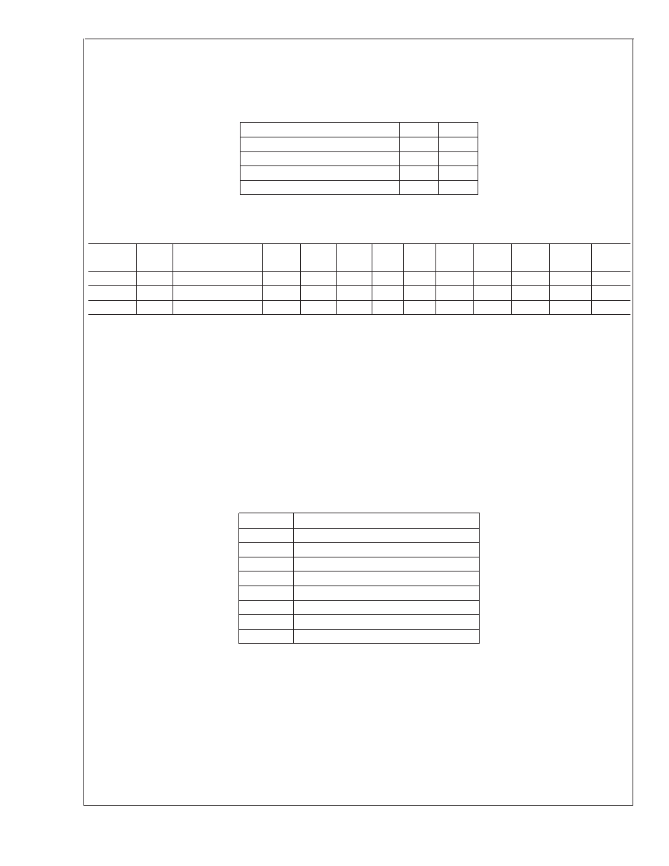
4.14 Registers 5C-5Eh: Fan Configuration
Register
Address
Read/
Write
Register
Name
Bit 7
(MSB)
Bit 6
Bit 5
Bit 4
Bit 3
Bit 2
Bit 1
Bit 0
(LSB)
Default
Value
Lock?
5Ch
R/W
Fan1 Configuration
ZON2
ZON1
ZON0
INV
RES
SPIN2
SPIN1
SPIN0
62h
U
5Dh
R/W
Fan2 Configuration
ZON2
ZON1
ZON0
INV
RES
SPIN2
SPIN1
SPIN0
62h
U
5Eh
R/W
Fan3 Configuration
ZON2
ZON1
ZON0
INV
RES
SPIN2
SPIN1
SPIN0
62h
U
This register becomes Read Only when the Ready/Lock/Start/Override register Lock bit is set. Any further attempts to write to this
register shall have no effect. After power up the default value is used whenever the Ready/Lock/Start/Override register Start bit
is cleared even though modifications to this register are possible.
Bits [7:5] Zone/Mode
Bits [7:5] of the Fan Configuration registers associate each fan with a temperature sensor. When in Auto Fan Mode the fan will
be assigned to a zone, and its PWM duty cycle will be adjusted according to the temperature of that zone. If ‘Hottest’ option is
selected (101 or 110), the fan will be controlled by the hottest of zones 2 and 3, or of zones 1, 2, and 3. To determine the ‘Hottest’
zone the PWM level for each zone is calculated then the the highest PWM value is selected. When in manual control mode, the
Current PWM duty registers (30h-32h) become Read/Write. It is then possible to control the PWM outputs with software by writing
to these registers. When the fan is disabled (100) the corresponding PWM output should be driven low (or high, if inverted).
Zone 1: External Diode 1 (processor)
Zone 2: Internal Sensor
Zone 3: External Diode 2
TABLE 4. Fan Zone Setting
ZON[2:0]
Fan Configuration
000
Fan on zone 1 auto
001
Fan on zone 2 auto
010
Fan on zone 3 auto
011
Fan always on full
100
Fan disabled
101
Fan controlled by hottest of zones 2, 3
110
Fan controlled by hottest of zones 1, 2, 3
111
Fan manually controlled (Test Mode)
Bit [4] PWM Invert
Bit [4] inverts the PWM output. If set to 0, 100% duty cycle will yield an output that is always high. If set to 1, 100% duty cycle
will yield an output that is always low.
Bit [3] Reserved
Bits [2:0] Spin Up
Bits [2:0] specify the ‘spin up’ time for the fan. When a fan is being started from a stationary state, the PWM output is held at 100%
duty cycle for the time specified in the table below before scaling to a lower speed.
LM96000
www.national.com
18