2 register 75h: fan spin-up mode, 23 undefined registers, 0 xor test mode – Rainbow Electronics LM96000 User Manual
Page 26: Functional description
Functional Description
(Continued)
•
Mode 2: This mode is optimized for accurate RPM readings and activates circuitry that extends the lower side of the RPM
reading as shown in the following table.
•
Mode 3: This mode minimizes the effect on the RPM setting and activates circuitry that extends the lower side of the RPM
reading as shown in the following table.
PWM Frequency
Mode 0 and 1 Minimum RPM
Mode 2 and 3 Minimum RPM
10.01
841
210
15.02
1262
315
23.14
1944
420
30.04
2523
420
38.16
3205
420
47.06
3953
420
61.38
5156
420
94.12
7906
420
This register is not effected when the Ready/Lock/Start/Override register Lock bit is set. After power up the default value is used
whenever the Ready/Lock/Start/Override register Start bit is cleared even though modifications to this register are possible.
4.22.2 Register 75h: Fan Spin-up Mode
Register
Address
Read/
Write
Register
Name
Bit 7
(MSB)
Bit 6 Bit 5 Bit 4 Bit 3
Bit 2
Bit 1
Bit 0
(LSB)
Default
Value
Lock?
75h
R/W
Fan Spin-up Mode
RES
RES
RES
RES
RES
PWM3 SU PWM2 SU PWM1 SU
7h
U
The PWM SU bit configures the PWM spin-up mode. If PWM SU is cleared the spin-up time will terminate after time programmed
by the Fan Configuration register has elapsed. When set to a 1, the spin-up time will terminate early if the TACH reading exceeds
the Tach Minimum value or after the time programmed by the Fan Configuration register has elapsed, whichever occurs first.
This register becomes Read Only when the Ready/Lock/Start/Override register Lock bit is set. Any further attempts to write to this
register shall have no effect. After power up the default value is used whenever the Ready/Lock/Start/Override register Start bit
is cleared even though modifications to this register are possible.
4.23 Undefined Registers
Any reads to undefined registers will always return 00h. Writes to undefined registers will have no effect and will not return an
error.
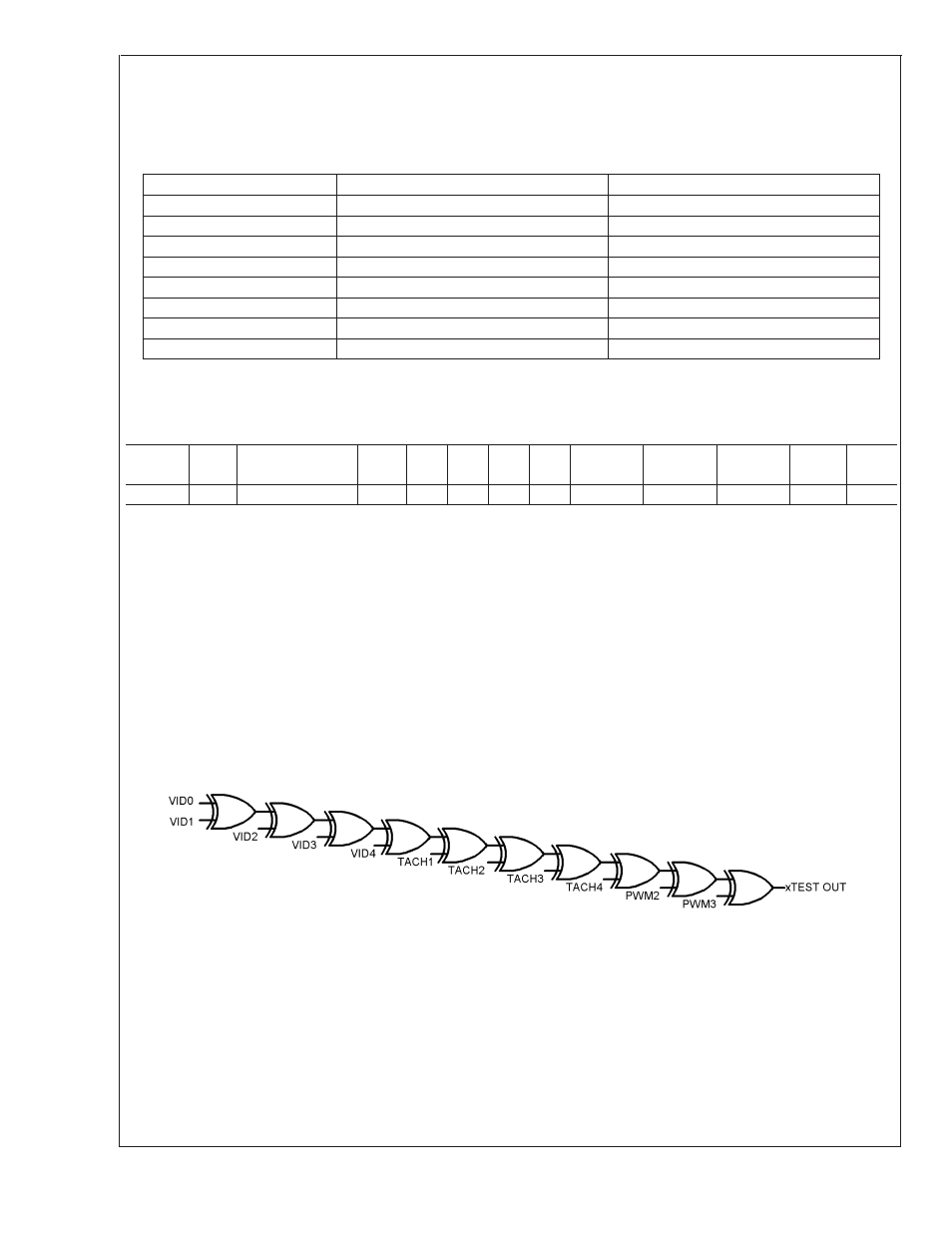
5.0 XOR TEST MODE
The LM96000 incorporates a XOR tree test mode. When the test mode is enabled by setting the “XEN” bit high in the Test
Register at address 6Fh via the SMBus, the part will enter XOR test mode.
Since the test mode an XOR tree, the order of the signals in the tree is not important. SMBDAT and SMBCLK are not to be
included in the test tree.
20084608
LM96000
www.national.com
26