Rainbow Electronics BTD-434 User Manual
Page 2
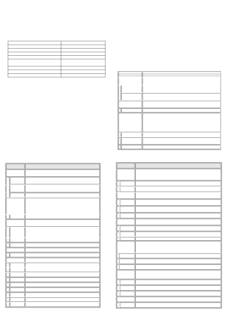
3.1.2. Slide Switch
The slide switch is used to set the adaptor as a DTE (to the side of antenna
connector) or a DCE (to the side of RS232 connector).
3.1.3. Power Supply
The adaptor can be powered via:
z
An AC/DC converter (output power: +5 to +9 V DC/300 mA)
z A
USB
cable
z
Pin 9 of the D SUB 9-pin connector
3.1.4. LED Status
The following is LED status information.
Status
Description
Power LED off
No power supply.
Power LED on
Firmware is running OK.
Link LED off
No pairing established.
Link LED fast (0.1 sec) blinking
Pairing (slave or master mode).
Link LED fast (0.3 sec) blinking
Discoverable and waiting for a
connection (slave mode).
Link LED slow (0.9 sec) blinking
Inq
uiring (master mode).
Link LED very slow (1.2 sec) blinking
Connectin
g (master mode).
Link LED steadily on
Connection established.
3.2. Installation Procedure
Step 1: If provided with an external antenna, assemble it to the adaptor body.
Step 2: Plug the adaptor into the COM port of device.
Step 3: Adjust the slide switch, depending on whether the device is a DTE or DCE.
Step 4: Power the adaptor on.
Step 5: Configure the adaptor if necessary.
4. Usage
You can reprogram the default settings on the adaptor using HyperTerminal.
4.1 HyperTerminal Settings
z Bits per second: 19200 bps (baud rate)
z Data bit: 8
z Parity:
None
z Stop bit: 1
z Flow control: H/W
4.2 Configuration
4.2.1 Configuration Start-up
Step 1: Plug the adaptor into a COM port of PC.
Step 2: Power the adaptor on.
Step 3: Create a HyperTerminal file.
-5 -
Step 4: On the interface of the new HyperTerminal file, click Properties button.
Step 5: Select the COM port where the adaptor is attached to your PC and set the port
properties as described in section 4.1 HyperTerminal Settings.
Step 6: Input "A" in the file and then press
If no echo, that is, nothing is displayed when you input "A", it indicates that the
baud rate is incorrect. Ensure that the baud rate is 19200 bps.
Step 7: Input "AT", and then press
"OK" is displayed.
If necessary, reprogram the configuration of adaptor using AT commands. For related
commands, please refer to section 4.3 AT Command Set.
4.2.1 Master Role Configuration
You can use "ATR0" to change the adaptor to the master role. When the adaptor is in
the master role, you can use "ATO1" to manually set up a connection and "ATF?" to
find the device you want to connect.
4.5. AT Command Set
The following is the AT command set for the local adaptor in the command mode
(that is, the local adaptor is in the disconnection state). All the commands and
parameters are case insensitive.
Command
Description
A
This command is used to establish a connection.
It is available only when the adaptor is in the master role.
A
Connect the adaptor to a specified Bluetooth device.
It is available only when "ATD=xxxxxxxxxxxx" is executed.
A1-A8
Connect the adaptor to a Bluetooth device in the neighborhood found
through "ATF?".
B
This command is used to display the Bluetooth address of the local
adaptor.
B?
Inquire the Bluetooth address of the local adaptor.
D
For security purpose, this command is used to specify a unique remote
Bluetooth serial adaptor to be connected.
In the master role, the adaptor pairs and connects with the designated
remote slave address.
If the adaptor is in the slave mode, this command is a filter condition to
accept the inquiry of the master device.
D=xxxxxxxxxxxx
"xxxx-xx-xxxxxx" is a string of 12 hexadecimal digits.
D0
Restore the status in which the adaptor can connect with any remote
address.
D?
Inquiry the designated address that can be paired and connected.
-6 -
Command
Description
E
This command is used to specify whether the adaptor echoes characters
received from the UART back to the DTE/DCE.
E0
Command characters received from the UART are not echoed back to the
DTE/DCE.
E1 (default)
Command characters received from the UART are echoed back to the
DTE/DCE.
E?
Inquire the current setting.
F
This command is used to search for any Bluetooth device in the
neighborhood within one minute. When one minute is up, the names and
addresses of devices if found will be listed with an ending message.
This command is available only when the adaptor is in the master role.
F?
Inquire Bluetooth devices in the neighborhood.
H
This command is used to specify whether the adaptor can be discovered
or connected by remote devices.
H0
The adaptor enters the undiscoverable mode. If a pair has been made,
the original connection can be resumed. But other remote master device
cannot discover this adaptor.
H1 (default) The adaptor enters the discoverable mode.
H?
Inquire the current setting.
I
This command is used to inquiry the firmware version.
I?
Inquire the version codes.
L
This command is used to specify the baud rate of COM port.
L0
4800 bps
L1
9600 bps
L2 (default) 19200 bps
L3
38400 bps
L4
57600 bps
L5
115200 bps
L6
230.4 Kbps
L7
460.8 Kbps
L?
Inquire the current baud rate.
- 7 -
Command
Description
N
This command is used to specify a name for the adaptor.
You can specify a friendly name using 0 to 9, A to Z, a to z, space and –, which are
all valid characters. Note that "first space or -, last space or – isn’t permitted". The
default name is “Serial Adaptor”.
N=xxxxxx
"xxxxxx" is a character string with a maximal length of 16.
N?
Inquire the name of the local adaptor.
O
This command is used to enable/disable auto-connection feature.
It is available only when the adaptor is in the master role.
O0 (Default) Automatically connect the adaptor to a device specified by "ATD" or any available
device if "ATD=xxxxxxxxxxxx" is not executed.
O1
Disable auto-connection feature. After it is executed, you need to execute "ATA" to
manually connect a remote device.
O?
Inquire the current setting.
P
This command is used to specify a PIN. The default PIN is "1234". Paired adaptors
should have a same PIN.
P=xxxx
"xxxx" is a 4-digit string.
P0
Cancel authentication by PIN.
P?
Inquire the current PIN.
Q
The command is used to decide whether result messages are sent back to the
DTE/DCE when AT commands are executed.
The result messages are: OK/ERROR for command execution, or
CONNECT/DISCONNECT for connection status.
Q0 (default)
Result messages are back to the DTE/DCE.
Q1
Result messages are not back to the DTE/DCE.
Q?
Inquire the current setting.
R
This command is used to specify whether the adaptor is in the master or slave role.
If the device role is changed, the adaptor will reboot and all paired addresses will be
cleared.
R0
Set the adaptor to the master role.
R1 (default) Set the adaptor to the slave role.
R?
Inquire the current role of the adaptor.
Z
This command is used to restore the default settings and originate a warm start.
Z0
Restore the default settings (e.g. 19200 bps).
- 8-
3.1.2. Slide Switch
The slide switch is used to set the adaptor as a DTE (to the side of antenna
connector) or a DCE (to the side of RS232 connector).
3.1.3. Power Supply
The adaptor can be powered via:
z
An AC/DC converter (output power: +5 to +9 V DC/300 mA)
z A
USB
cable
z
Pin 9 of the D SUB 9-pin connector
3.1.4. LED Status
The following is LED status information.
Status
Description
Power LED off
No power supply.
Power LED on
Firmware is running OK.
Link LED off
No pairing established.
Link LED fast (0.1 sec) blinking
Pairing (slave or master mode).
Link LED fast (0.3 sec) blinking
Discoverable and waiting for a
connection (slave mode).
Link LED slow (0.9 sec) blinking
Inq
uiring (master mode).
Link LED very slow (1.2 sec) blinking
Connectin
g (master mode).
Link LED steadily on
Connection established.
3.2. Installation Procedure
Step 1: If provided with an external antenna, assemble it to the adaptor body.
Step 2: Plug the adaptor into the COM port of device.
Step 3: Adjust the slide switch, depending on whether the device is a DTE or DCE.
Step 4: Power the adaptor on.
Step 5: Configure the adaptor if necessary.
4. Usage
You can reprogram the default settings on the adaptor using HyperTerminal.
4.1 HyperTerminal Settings
z Bits per second: 19200 bps (baud rate)
z Data bit: 8
z Parity:
None
z Stop bit: 1
z Flow control: H/W
4.2 Configuration
4.2.1 Configuration Start-up
Step 1: Plug the adaptor into a COM port of PC.
Step 2: Power the adaptor on.
Step 3: Create a HyperTerminal file.
-5 -
Step 4: On the interface of the new HyperTerminal file, click Properties button.
Step 5: Select the COM port where the adaptor is attached to your PC and set the port
properties as described in section 4.1 HyperTerminal Settings.
Step 6: Input "A" in the file and then press
If no echo, that is, nothing is displayed when you input "A", it indicates that the
baud rate is incorrect. Ensure that the baud rate is 19200 bps.
Step 7: Input "AT", and then press
"OK" is displayed.
If necessary, reprogram the configuration of adaptor using AT commands. For related
commands, please refer to section 4.3 AT Command Set.
4.2.1 Master Role Configuration
You can use "ATR0" to change the adaptor to the master role. When the adaptor is in
the master role, you can use "ATO1" to manually set up a connection and "ATF?" to
find the device you want to connect.
4.4. AT Command Set
The following is the AT command set for the local adaptor in the command mode
(that is, the local adaptor is in the disconnection state). All the commands and
parameters are case insensitive.
Command
Description
A
This command is used to establish a connection.
It is available only when the adaptor is in the master role.
A
Connect the adaptor to a specified Bluetooth device.
It is available only when "ATD=xxxxxxxxxxxx" is executed.
A1-A8
Connect the adaptor to a Bluetooth device in the neighborhood found
through "ATF?".
B
This command is used to display the Bluetooth address of the local
adaptor.
B?
Inquire the Bluetooth address of the local adaptor.
D
For security purpose, this command is used to specify a unique remote
Bluetooth serial adaptor to be connected.
In the master role, the adaptor pairs and connects with the designated
remote slave address.
If the adaptor is in the slave mode, this command is a filter condition to
accept the inquiry of the master device.
D=xxxxxxxxxxxx
"xxxx-xx-xxxxxx" is a string of 12 hexadecimal digits.
D0
Restore the status in which the adaptor can connect with any remote
address.
D?
Inquiry the designated address that can be paired and connected.
-6 -
Command
Description
N
This command is used to specify a name for the adaptor.
You can specify a friendly name using 0 to 9, A to Z, a to z, space and –, which are
all valid characters. Note that "first space or -, last space or – isn’t permitted". The
default name is “Serial Adaptor”.
N=xxxxxx
"xxxxxx" is a character string with a maximal length of 16.
N?
Inquire the name of the local adaptor.
O
This command is used to enable/disable auto-connection feature.
It is available only when the adaptor is in the master role.
O0 (Default) Automatically connect the adaptor to a device specified by "ATD" or any available
device if "ATD=xxxxxxxxxxxx" is not executed.
O1
Disable auto-connection feature. After it is executed, you need to execute "ATA" to
manually connect a remote device.
O?
Inquire the current setting.
P
This command is used to specify a PIN. The default PIN is "1234". Paired adaptors
should have a same PIN.
P=xxxx
"xxxx" is a 4-digit string.
P0
Cancel authentication by PIN.
P?
Inquire the current PIN.
Q
The command is used to decide whether result messages are sent back to the
DTE/DCE when AT commands are executed.
The result messages are: OK/ERROR for command execution, or
CONNECT/DISCONNECT for connection status.
Q0 (default)
Result messages are back to the DTE/DCE.
Q1
Result messages are not back to the DTE/DCE.
Q?
Inquire the current setting.
R
This command is used to specify whether the adaptor is in the master or slave role.
If the device role is changed, the adaptor will reboot and all paired addresses will be
cleared.
R0
Set the adaptor to the master role.
R1 (default) Set the adaptor to the slave role.
R?
Inquire the current role of the adaptor.
Z
This command is used to restore the default settings and originate a warm start.
Z0
Restore the default settings (e.g. 19200 bps).
- 8-
Command
Description
E
This command is used to specify whether the adaptor echoes characters
received from the UART back to the DTE/DCE.
E0
Command characters received from the UART are not echoed back to the
DTE/DCE.
E1 (default)
Command characters received from the UART are echoed back to the
DTE/DCE.
E?
Inquire the current setting.
F
This command is used to search for any Bluetooth device in the
neighborhood within one minute. If any device is found, its name and
address will be listed. The search ends with a message "Inquiry ends. xx
device(s) found."
This command is available only when the adaptor is in the master role.
F?
Inquire Bluetooth devices in the neighborhood.
H
This command is used to specify whether the adaptor can be discovered
or connected by remote devices.
H0
The adaptor enters the undiscoverable mode. If a pair has been made,
the original connection can be resumed. But other remote master device
cannot discover this adaptor.
H1 (default) The adaptor enters the discoverable mode.
H?
Inquire the current setting.
I
This command is used to inquiry the firmware version.
I?
Inquire the version codes.
L
This command is used to specify the baud rate of COM port.
L0
4800 bps
L1
9600 bps
L2 (default) 19200 bps
L3
38400 bps
L4
57600 bps
L5
115200 bps
L6
230.4 Kbps
L7
460.8 Kbps
L?
Inquire the current baud rate.
- 7 -
Step 4: On the interface of the new HyperTerminal file, click Properties button.
Step 5: Select the COM port where the adaptor is attached to your PC and set the port
properties as described in section 4.1 HyperTerminal Settings.
Step 6: Input "A" in the file and then press
If no echo, that is, nothing is displayed when you input "A", it indicates that the
baud rate is incorrect. Ensure that the baud rate is 19200 bps.
Step 7: Input "AT", and then press
"OK" is displayed.
If necessary, reprogram the configuration of adaptor using AT commands. For related
commands, please refer to section 4.3 AT Command Set.
4.2.1 Master Role Configuration
You can use "ATR0" to change the adaptor to the master role. When the adaptor is in
the master role, you can use "ATO1" to manually set up a connection and "ATF?" to
find the device you want to connect.
4.3. AT Command Set
The following is the AT command set for the local adaptor in the command mode
(that is, the local adaptor is in the disconnection state). All the commands and
parameters are case insensitive.
Command
Description
A
This command is used to establish a connection.
It is available only when the adaptor is in the master role.
A
Connect the adaptor to a specified Bluetooth device.
It is available only when "ATD=xxxxxxxxxxxx" is executed.
A1-A8
Connect the adaptor to a Bluetooth device in the neighborhood found
through "ATF?".
B
This command is used to display the Bluetooth address of the local
adaptor.
B?
Inquire the Bluetooth address of the local adaptor.
D
For security purpose, this command is used to specify a unique remote
Bluetooth serial adaptor to be connected.
In the master role, the adaptor pairs and connects with the designated
remote slave address.
If the adaptor is in the slave mode, this command is a filter condition to
accept the inquiry of the master device.
D=xxxxxxxxxxxx
"xxxx-xx-xxxxxx" is a string of 12 hexadecimal digits.
D0
Restore the status in which the adaptor can connect with any remote
address.
D?
Inquiry the designated address that can be paired and connected.
-6 -
3.1.2. Slide Switch
The slide switch is used to set the adaptor as a DTE (to the side of antenna
connector) or a DCE (to the side of RS232 connector).
3.1.3. Power Supply
The adaptor can be powered via:
z
An AC/DC converter (output power: +5 to +9 V DC/300 mA)
z A
USB
cable
z
Pin 9 of the D SUB 9-pin connector
3.1.4. LED Status
The following is LED status information.
Status
Description
Power LED off
No power supply.
Power LED on
Firmware is running OK.
Link LED off
No pairing established.
Link LED fast (0.1 sec) blinking
Pairing (slave or master mode).
Link LED fast (0.3 sec) blinking
Discoverable and waiting for a
connection (slave mode).
Link LED slow (0.9 sec) blinking
Inq
uiring (master mode).
Link LED very slow (1.2 sec) blinking
Connectin
g (master mode).
Link LED steadily on
Connection established.
3.2. Installation Procedure
Step 1: If provided with an external antenna, assemble it to the adaptor body.
Step 2: Plug the adaptor into the COM port of device.
Step 3: Adjust the slide switch, depending on whether the device is a DTE or DCE.
Step 4: Power the adaptor on.
Step 5: Configure the adaptor if necessary.
4. Usage
You can reprogram the default settings on the adaptor using HyperTerminal.
4.1 HyperTerminal Settings
z Bits per second: 19200 bps (baud rate)
z Data bit: 8
z Parity:
None
z Stop bit: 1
z Flow control: H/W
4.2 Configuration
4.2.1 Configuration Start-up
Step 1: Plug the adaptor into a COM port of PC.
Step 2: Power the adaptor on.
Step 3: Create a HyperTerminal file.
-5 -