General description – Rainbow Electronics ATA5757 User Manual
Page 4
4
ATA5756/ATA5757 [Preliminary]
4702D–RKE–02/04
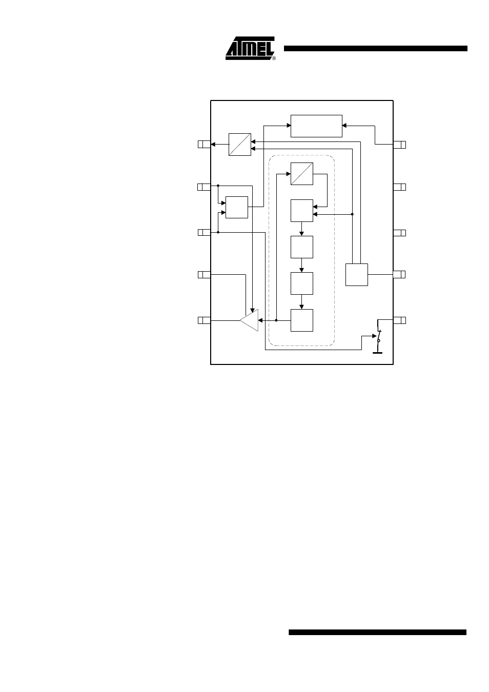
Figure 3. Block Diagram
General Description
This fully integrated PLL transmitter allows the design of simple, low-cost RF miniature
transmitters for TPM and RKE applications. The VCO is locked to 24
×
f
XTAL
/32
×
f
XTAL
for ATA5756/ATA5757. Thus, a 13.125 MHz/13.56 MHz crystal is needed for a
315 MHz/433.92 MHz transmitter. All other PLL and VCO peripheral elements are
integrated.
The XTO is a series resonance (current mode) oscillator. Only one capacitor and a
crystal connected in series to GND are needed as external elements in an ASK system.
The internal FSK switch, together with a second capacitor, can be used for FSK
modulation.
The crystal oscillator needs typically 0.6 ms until the CLK output is activated if a crystal
as defined in the electrical characteristics is used (e.g., TPM crystal). For most crystals
used in RKE systems, a shorter time will result.
The CLK output is switched on if the amplitude of the current flowing through the crystal
has reached 35% to 80% of its final value. This is synchronized with the 1.64/1.69 MHz
CLK output. As a result, the first period of the CLK output is always a full period. The
PLL is then locked <250 µs after CLK output activation. This means an additional wait
time of
≥
250 µs is necessary before the PA can be switched on and the data transmis-
sion can start. This results in a significantly lower time of about 0.85 ms between
enabling the ATA5756/ATA5757 and the beginning of the data transmission which saves
battery power especially in tire pressure monitoring systems.
CLK
FSK
ANT2
ANT1
ENABLE
GND
VS
XTO2
1
3
4
5
6
8
9
10
VCO
LF
CP
f
24/
XTO
PLL
PA
f
8
Power up/down
ATA5756 /
ATA5757
PFD
ASK
2
XTO1
7
EN
OR
EN
Ampl. OK
32