Rainbow Electronics ATA5757 User Manual
Page 10
10
ATA5756/ATA5757 [Preliminary]
4702D–RKE–02/04
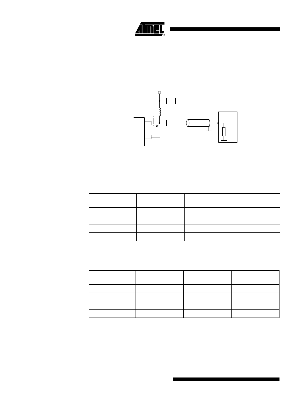
Output power measurement can be done with the circuit as shown in Figure 9. Please
note that the component values must be changed to compensate the individual board
parasitics until the ATA5756/ATA5757 has the right load impedance. Also, the damping
of the cable used to measure the output power must be calibrated.
Figure 9. Output Power Measurement ATA5756/ATA5757
Table 2 and Table 3 show the output power and the supply current versus temperature
and supply voltage.
Table 2. Output Power and Supply Current versus Temperature and Supply
Voltage for the ATA5756 with Z
Load
= 380
Ω
+ j340
Ω
(Correlation Tested)
Ambient
Temperature
V
S
= 2.0 V
(dBm/mA)
V
S
= 3.0 V
(dBm/mA)
V
S
= 3.6 V
(dBm/mA)
T
amb
= -40°C
3.1 ±1.5 / 7.2
6.1 +2/-3 / 7.7
7.1 +2/-3 / 7.9
T
amb
= +25°C
3.0 ±1.5 / 7.5
6.0 ±2 / 8.1
7.4 ±2 / 8.3
T
amb
= +85°C
3.0 ±1.5 / 7.5
5.8 +2/-3 / 8.2
7.2 +2/-3 / 8.5
T
amb
= +125°C
2.5 ±1.5 / 7.6
5.5 +2/-3 / 8.2
6.5 +2/-3 / 8.5
Table 3. Output Power and Supply Current versus Temperature and Supply
Voltage for the ATA5757 with Z
Load
= 280
Ω
+ j310
Ω
(Correlation Tested)
Ambient
Temperature
V
S
= 2.0 V
(dBm/mA)
V
S
= 3.0 V
(dBm/mA)
V
S
= 3.6 V
(dBm/mA)
T
amb
= -40°C
3.3 ±1.5 / 7.6
6.2 +2/-3 / 8.1
7.1 +2/-3 / 8.4
T
amb
= +25°C
3.0 ±1.5 / 8.0
6.0 ±2 / 8.5
7.5 ±2 / 8.8
T
amb
= +85°C
2.8 ±1.5 / 8.0
5.7 +2/-3 / 8.6
6.8 +2/-3 / 8.8
T
amb
= +125°C
2.7 ±1.5 / 8.1
5.5 +2/-3 / 8.7
6.6 +2/-3 / 8.9
~
~
ANT2
ANT1
R
in
Power
meter
C
1
= 1n
L
1
= 68 nH/ 39 nH
C
2
= 2.2 pF/1.8 pF
Z
Lopt
V
S
Z = 50
Ω
50
Ω